A Submarine Telephone Cable with Submerged Repeaters
Cite this paper
J. J. Gilbert, "A Submarine Telephone Cable with Submerged Repeaters," Bell System Technical Journal, vol. 30, no. 1, January 1951, pp. 65–87.
Full text
A Submarine Telephone Cable with Submerged Repeaters
By J. J. GILBERT
(Manuscript Received Sept. 11, 1950)
The paper describes the recently installed Key West-Havana submarine cable telephone system in which repeaters designed for long life are incorporated in the cable structure and are laid as part of the cable.
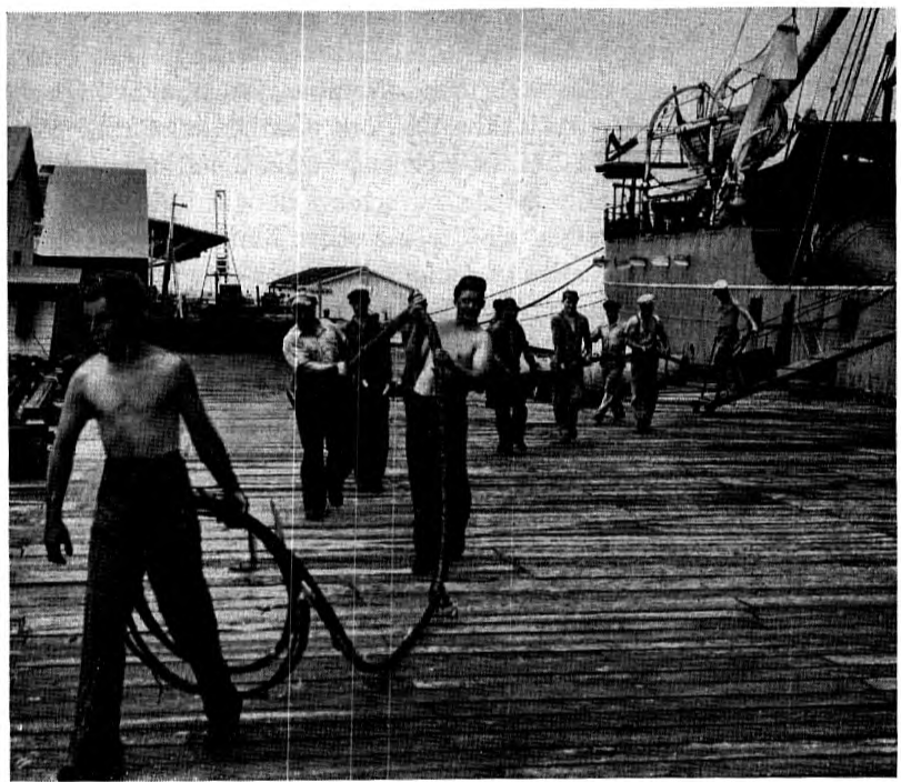
IN APRIL of last year there was installed between Key West, Florida, and Havana, Cuba, a submarine telephone cable system involving a radical departure from the conventional art of long distance submarine telephony. This departure consisted of the inclusion within the armor of the submarine cable of electron tube repeaters which are designed to pass through the cable laying machinery and sink to the ocean bottom like a length of cable, and which, over an extended period of perhaps twenty years, should not require servicing for the purpose of changing electron tubes or defective circuit elements. The repeater has the appearance of a bulge in the cable about three inches in diameter and tapering off in both directions to the cable diameter of a little over an inch. The total length of the bulge including the taper at each end is about 35 feet. The bulge is flexible enough so that it can conform to the curvature of the brake drum and of the various sheaves in the laying gear on the cable ship. A repeater, with stub cables, is shown in Fig. 1.
Historical
The new cable system, comprising cables Nos. 5 and 6 of the Cuban-American Telephone and Telegraph Company, represents another step in the development of telephonic communication between the United States and Cuba, which has presented many interesting problems. Natural conditions make it difficult, if not impossible, to employ some of the usual methods of communication. One such condition is the absence of high ground in Florida that would permit the use of economic radio systems. Another is the stretch of water between Florida and Cuba, which, in places, is as much as 6,000 feet in depth and which restricts the type of cable that can be used. The practical solution has been to go from the point of contact with the Bell System toll lines at Miami, over the Keys to Key West by land line (with some water crossings), thence to Havana, an air line distance of about 100 n.m., by submarine cable of the deep sea type of construction, having a single coaxial circuit, insulated with water resistant material. There p. 66 are problems involved in building and maintaining the Miami-Key West connections but these are outside the scope of the present article.
Telephone communication between the United States and Cuba was initiated in 1921, when three submarine cables were laid between Key West and Havana.1 Each cable provided a telephone circuit, operated on a two-wire basis, and two or more telegraph circuits, d-c. and a-c. The cables were continuously loaded with iron wire, insulated with gutta-percha and had return conductors consisting of copper tapes laid on the insulated core and exposed electrically to the sea water. These cables were the first ones to employ the copper return conductor, which has also been used in subsequent cables. The copper return was employed after a theoretical study had indicated that the armor and sea water, which for the low frequencies then involved in cable telegraphy furnished a low resistance return conductor, would not be satisfactory at voice and higher frequencies. At these frequencies skin effect causes the return current to concentrate in the armor wires, which are naturally poor p. 67 conductors for alternating currents, and this makes the resistance of the return path rise to undesirable values. The copper return effectively removes the armor wire and sea water from the transmission circuit at all but very low frequencies. This has the further advantage of reducing the exposure of the circuit to static noise.
Although the iron wire loading was very effective in reducing attenuation in the voice range, the eddy current resistance due to the loading wire made itself felt to a rapidly increasing degree for frequencies above the voice band. Consequently, when additional circuits were required some years later and it was decided to extend the frequency range in order to make use of newly developed carrier frequency equipment, it was necessary to dispense with magnetic loading. In 1930 the Key West-Havana No. 4 cable was laid embodying new materials and novel principles of design.2 The insulating material in this case was paragutta, which had been recently developed by the Laboratories, and which possessed electrical characteristics and stability much superior to gutta-percha. An intensive study had been made of the design of coaxial cables for carrier frequencies with the aim of obtaining optimum electrical performance by proper proportioning and construction of the conductors and these principles were employed in the new cable. Initially, three carrier telephone circuits were obtained on the No. 4 cable using the equivalent four-wire method, with separate frequency bands for transmission in opposite directions. The cable had been designed with considerable transmission margin and in 1940 the need for additional circuits to Cuba resulted in the installation of new terminal equipment which enabled it to provide seven two-way high quality circuits on an equivalent four-wire basis.
The Key West-Havana No. 4 cable design has proved very popular in other parts of the world. Several such cables have been laid between England and the Continent and between England and Ireland, between Australia and Tasmania, and others were used in connection with the war effort. A cable of this design has also been laid between two of the Japanese islands.
Submerged Repeaters
The demands for circuits to Havana continued to grow, and, after the close of World War II, the time appeared ripe for making use of a new development which had just come to a head in the Laboratories after a period of experimentation.3 This development was the submerged repeater. The need for periodic strengthening of signals transmitted over considerable distances is about the same in submarine cables as it is in land p. 68 lines and, as in land lines, the permissible spacing between repeaters usually diminishes as the desired frequency increases. The great difficulty in the case of submarine cable routes is that there are usually no land sites on which repeaters can be located. Artificial islands consisting of floating platforms or buoys have been proposed as a solution, but ocean currents and storms have disastrous effects on such structures. Interruptions due to such causes would make it difficult to meet the requirement on continuity of service which is necessary in the case of important telephone circuits. Therefore, it appeared that the safest place for a submarine cable repeater is on the ocean bottom.
Requirements on Repeater
The decision to place the repeater on the ocean bottom resulted in special requirements on the structure the first of which is that it be capable of resisting the considerable hydrostatic pressure that is encountered in deep water. It also seemed desirable that the operation of getting the repeater overboard from the cable ship should not impede the smooth functioning of the laying process. The best way of meeting this requirement appeared to be to make the repeater structure flexible, within practicable limits, and as small as possible in diameter so that it could pass around the drum and sheaves of the laying gear like any length of cable.
In order to make such a repeater attractive from operating and commercial points of view another requirement was necessary, namely, that the electrical circuit elements of the repeater, including electron tubes, resistances, condensers and coils be designed for long life under operating conditions, so that there would be assurance of freedom from trouble or need of replacement of parts over a long period, perhaps twenty years or more. Servicing of the repeater would be in the nature of a cable repair, and the repair of a submarine cable is something not to be sought after. The procedure is apt to be expensive and time consuming, due to circumstances beyond control such as bad weather or lack of availability of a repair ship; and the disturbance of the cable involved in lifting it to the surface and dropping it again, possibly in something of a heap, is not desirable. It is obvious that the requirement on long life of circuit elements presents a difficult problem, especially in view of the fact that the space available for these elements is minimized in order to keep the repeater diameter small.
There was still another requirement on circuit elements, that of ruggedness. The stresses involved in laying cables in deep waters are quite considerable. The cable is under a tension of several thousand pounds and "incidents" might occur which would have no effect on an ordinary cable but which might result in dangerous shocks to the delicate elements of the repeater.
Also, as a consequence of the cable tension, the armor unlays somewhat; and this imposes twist and elongation on the interior structure, either coaxial circuit or repeater housing. The cable circuit can be designed to withstand this distortion, but the repeater housing is much more susceptible to damage from this cause.
The Repeater Housing
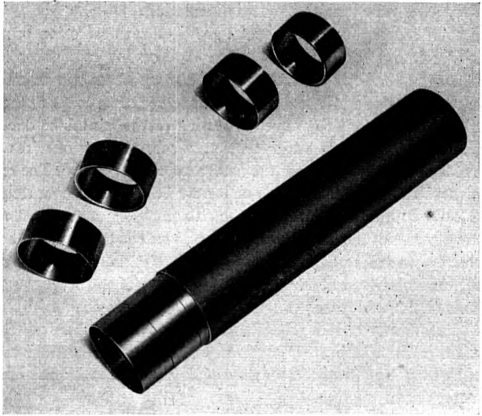
The requirements on flexibility and water-tightness under ocean bottom pressures were the factors of outstanding influence in the design of the repeater housing and of the end seals by means of which the cable enters and leaves the housing. In the present form the housing consists of a long tube of soft copper 1¾ inches in diameter and .03 inch thick, supported internally against collapse under sea bottom pressure by an assemblage of abutting steel rings, each ¾″ wide, and given a degree of rigidity by means of thinner steel rings of the same width overlaying and staggered relative to the thicker rings. When this structure is sealed at the ends it is capable of withstanding pressures as high as 10,000 pounds per square inch and it can be bent to a radius as small as three feet without undue distortion of the copper envelope. Details of the structure are shown in Fig. 2.
Into each end of the housing is led the insulated conductor of the cable by p. 70 means of a series of seals. The inner or vapor seal is of the glass-metal type especially developed for this particular purpose and capable of withstanding considerable hydrostatic pressures. Next in line there is a seal comprising a central brass tube and an external brass member, both vulcanized to rubber, which is joined to the insulating material of the cable. These seals are coaxial in form, the outer member in each case being brazed to the copper tube of the housing or an extension thereof. Finally a closely fitting "core tube" of copper, extending over the cable insulation for a distance of about seven feet, is brazed to an extension of the copper envelope of the housing, filled with vistac and sealed at the distant end by means of a neoprene sleeve joined firmly to the core tube and to the cable insulation.
The repeater housing and core tube are provided with corrosion protective layers and a bedding for the armor wires, the bedding over the core tube being built up in the form of a taper. The armor is a continuation of the cable armor wires with additional wires interspersed on account of the larger diameter of the repeater. To prevent twisting of the container due to the unlaying of the armor wires under tension, a second layer of wires with a direction of lay opposite to that of the main armor is employed. The repeater may be armored as part of the cable or it may be armored separately, with a stub on each end, and spliced into the cable.
The components of the housings and seals, as well as the complete armored housing, have been subjected to exhaustive tests of various sorts. The rubber-brass seal, for instance, was tested for penetration of moisture vapor over long periods of time. Methods of making this seal were checked by tension tests until a uniformly high degree of adhesion was obtained. Armored housings were tested on a laboratory setup in which laying conditions could be simulated by bending the structure under tension and in motion around a six foot diameter drum.
The Repeater Circuit
The diameter of the housing had been chosen originally on the assumption that the bulge caused by the repeater should not be more than two or three times the diameter of the cable proper in order to reduce the possibility of over-riding turns on the brake drum during laying. Mechanical tests indicated that this diameter was also safe from the standpoint of deformation of the copper envelope during bending. Accordingly, it was required that the repeater structure should be restricted in cross-section so as to fit inside this tube, with as much length as would be needed.
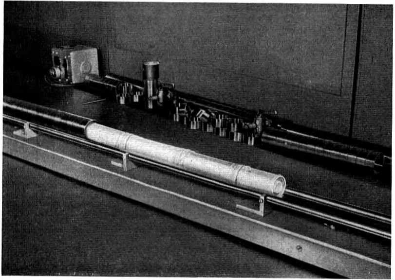
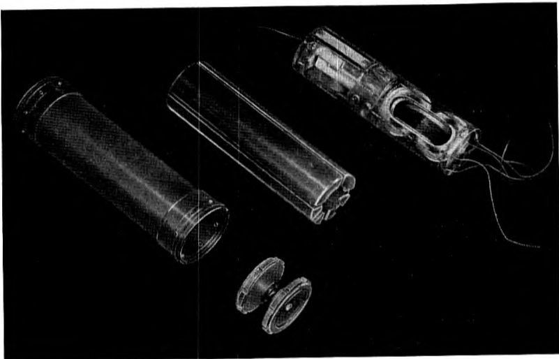
The problem then became one of packaging the elements involved in a high gain electron tube amplifier in the restricted space available. The method finally adopted is shown in Fig. 3. The completed amplifier consists of an p. 71 articulated assemblage of composite lucite cylinders, each about five inches long, successive units being held together by a spring assembly. Each lucite cylinder contains the related electrical elements of a particular part of the repeater circuit. The groups of smaller elements are mounted rigidly in a lucite form which slides into an insulating envelope consisting of two close fitting lucite shells and is held in place by end pieces of lucite. Eight copper tapes laid in axial slots between the shells and extending over several sections, where necessary, permit electrical interconnection of the various parts. A representative assemblage is shown in Fig. 4. In the case of the Key West-Havana repeater the complete assemblage is eighty-four inches long and comprises fifteen sections.
Circuit Elements
Early in the development general principles were developed regarding the type of circuit best suited for underwater repeaters and on this basis requirements were established on the characteristics necessary for the circuit elements, including electron tubes, and on their arrangement in the repeater. Decisions in such matters could not be arbitrary of course, but had to be carefully worked out in order to freeze designs as early as possible so as to facilitate the start of significant life tests.
The electron tube is the most important of the elements. Work had been p. 72 begun on a tube suitable for this use as far back as 1933. Thus, when a decision was made to lay the new cables, a long background of experience was drawn on in the manufacture of the tubes. Early models of the type had been operated on continuous life test for as long as ten years. Designed primarily for long life, the tube is a suppressor grid pentode with an indirectly heated cathode. Of rugged design to withstand the shocks of cable laying, the spacings between electrodes are relatively large. Unusual care was taken in manufacture to insure solid welds and to avoid the presence of loose particles. During various stages of assembly, rigorous inspections were made on all tubes by engineering personnel. Selection of tubes for use in the cable was based on a thorough examination of all details in the history of each tube, as well as the history of the group in which it was manufactured. All tubes which were candidates for the cable were aged several thousand hours before preliminary selection was made. In addition, other tubes from the same production group were further life tested several more thousand hours to establish the quality of the group. One early decision was to power repeaters by direct current fed from land over the cable conductor. The tube heaters connected in series would furnish plate and grid potentials. This was an important factor in setting the nominal power requirements for the tube, which are about ¼ ampere at 20 volts for heater supply and plate potentials of 40 to 60 volts.
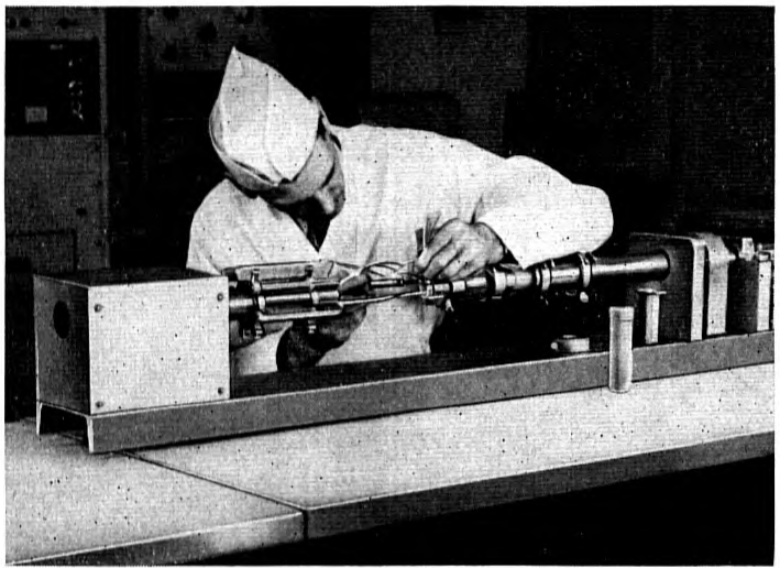
While the electron tube is usually the most vulnerable element in electrical circuits from the standpoint of life, attention must be given to other p. 73 elements—condensers, resistances, and coils—especially where they are subject to long continued application of electrical potentials, as in the case of power separation filters. The factors that determine the life and performance of these elements are not completely under control. It was felt, however, that the best assurance on dependability could be obtained by careful, conservative design and by manufacturing and assembling the elements into repeaters under the best possible conditions of cleanliness. An air conditioned space was provided for this purpose at the Murray Hill Laboratory. In addition to cleaning the air in this space, precautions were taken against the entrance of dirt by other means, for example, on the clothing or persons of operators. The humidity of the air was carefully controlled to prevent contamination from perspiration during handling of the parts. Manufacture was carried out by selected workmen, and the product was inspected at various stages by engineers. A view of one of the operations is given in Fig. 5.
Field Trials
Simulated laying tests in the laboratory covered a period of several years. Special pains had been taken to include as far as possible all aspects of the laying operation, even those which were judged to be free of hazard to the repeater. Tests were also made to determine the effect, if any, of the laying operation upon the electrical transmission characteristics of the cable. Likewise, comprehensive electrical tests had been made to insure that no unexpected p. 74 effects would be encountered due to the immersion of the repeater in water.
A large scale test was needed, however, to establish the practicability of the repeatered cable. This is because of the fact that during the laying operation the suspended length of cable trailing the ship may be as great as ten nautical miles or more, and in this length there occur complex mechanical phenomena which cannot be simulated in the laboratory with a great degree of assurance. After preliminary trials from a barge in Long Island Sound, a deep water test of the repeatered cable was made in 1948 in the Bahamas. The cable ship LORD KELVIN of the Western Union Telegraph Company was chartered for the purpose. Lengths of cable up to 15 n.m. were paid out along with repeaters in depths of water up to 2 n.m. Several repeaters were laid, measured while on the ocean bottom and then hauled back to the ship, a procedure that involves much more severe treatment than a mere laying operation. The repeater shown in Fig. 1 experienced this treatment. Tests were also made with repeater housings containing specially designed accelerometers to determine the shocks resulting from possible abuse during laying. The results indicated that the repeaters as well as the cable could take the punishment with considerable margin of safety.
The Transmission System
Designing the electrical circuit of the repeater was largely a matter of getting the most out of the long life electron tube in the way of stability of repeater gain and low modulation while obtaining as much gain as the system permits. For most efficient use of tubes and to simplify the structure a unidirectional repeater design was decided upon.
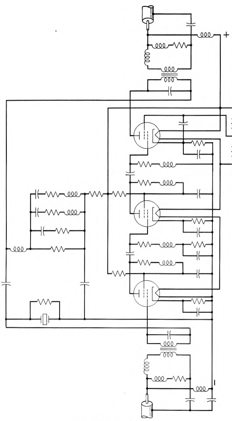
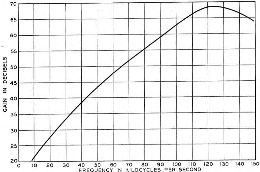
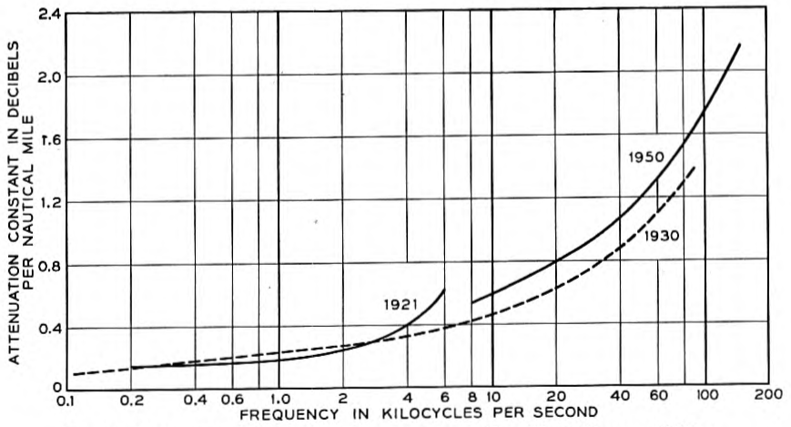
The repeater employed in the Key West-Havana cables has three stages with negative feed back, the circuit being as shown in Fig. 6. The gain frequency characteristic is shown in Fig. 7. The transmission band is from 12 kc. to 120 kc. The insertion gain at 108 kc., the top frequency employed in traffic, is 65 db. The repeater gain equalizes the loss of about 36 n.m. of cable, the attenuation frequency characteristic of which is shown in Fig. 8. For comparison the characteristics of the earlier cables are also shown.
The layout of the new repeatered cable installation is shown in Fig. 9. There are two cables, one for each direction of transmission. The East, or No. 5 cable, transmitting South, is 114.55 n.m. in length. The West, or No. 6 cable, transmits north and is 124.97 n.m. in length. Each cable has three repeaters spaced approximately 36 n.m. apart. Two of the six repeaters are in a depth of .9 n.m. and two in about .35 n.m. The last repeater in each cable is located as close as possible to deep water so as to strengthen the signal before it enters shallow water and land sections of cable where static p. 75 p. 76 noise and crosstalk might be picked up. In Havana the last repeater is located in a large vault on the beach. At Key West the last repeater is located close to Sand Key Light where the water begins to deepen.
At manholes near the shore at both ends the cables are spliced directly to underground cables running in ducts to the terminal equipment at the offices, a distance of three miles at Havana and one mile at Key West. The underground p. 77 p. 78 cables have the same coaxial circuit as the submarine cables but in place of the mechanical protection of jute and armor they are provided with electrical protection of helical steel tapes, layers of paper and over all a lead sheath.
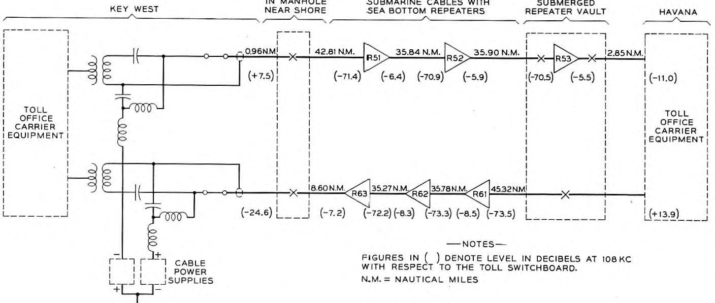
The 12 kc. to 108 kc. passband yields 24 channels in each cable, each channel occupying a band of 4 kc. The signal-to-noise ratio for these channels is about the same as for the same length of high grade carrier frequency circuit on land.
The Cable
The cable has a copper return, as in the case of the earlier installations, but differs from them in being insulated with polyethylene. It also involves some new principles of design that render the cable circuit less subject to change of electrical characteristics due to laying stresses. This is a matter of considerable importance in the case of a system with submerged repeaters, since after the cable has reached the bottom it is impossible to adjust the repeater to compensate for changes in cable attenuation during laying, a matter that in ordinary cables is taken care of by adjusting the equipment on shore.
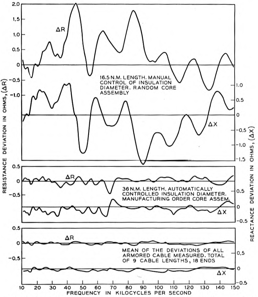
In order to avoid undesirable irregularities in transmission characteristics special precautions were taken during manufacture to obtain a higher than usual degree of uniformity of the cable impedance as seen by a repeater. Because of the wide transmission band, schemes heretofore employed for reducing the effect of the variation of impedance among the core lengths constituting the cable would have called for core lengths so short as to seriously increase the number of joints. The irregularities were therefore minimized by careful control of conductor and insulation diameters and by continuously insulating lengths of the order of 12 n.m., cutting them only as was necessary for handling, and reassembling the shorter lengths as far as possible in insulating order to assure random addition of reflections due to impedance irregularities. The success of this technique is evidenced by the impedance deviation curves shown in Fig. 10.
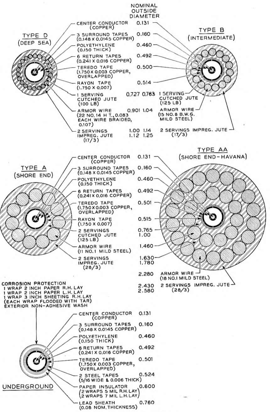
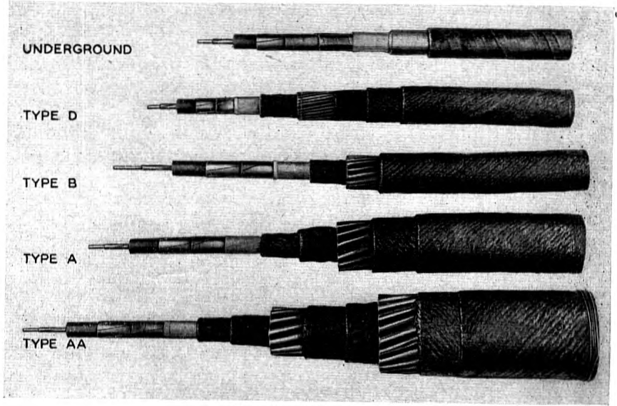
The structure of the cable is shown in Figs. 11 and 12. The central conductor consists of a solid wire .131 inch in diameter on which are laid three copper tape surrounds each .0145 inch thick and .148 inch wide, closely conforming to the solid wire. The interstices of the conductor are filled with polyethylene. The stranded conductor, .160 inch in diameter, is insulated with polyethylene to a diameter of .460 inch. Directly on the polyethylene insulation is laid the return conductor comprising six copper tapes, each approximately .016 inch thick by .241 inch wide, preshaped so that when in place they conform to the surface of the insulation. Both the return tapes and the tape surrounds of the central conductor have left hand lay. Over the return conductor is wound a teredo tape approximately .003 inch thick with overlap. Over all is the p. 79 cutched jute, the armor and the outer jute serving, to which are applied the usual cable compounds. Four types of armor are employed in the cable for use in various depths of water or for special shore conditions.
| Type | No. 5 Cable | No. 6 Cable |
|---|---|---|
| A | 14.31 | 12.65 |
| B | 25.60 | 31.22 |
| D | 72.73 | 76.17 |
| B | 1.44 | 4.39 |
| A | .16 | .18 |
| AA | .31 | .36 |
During the course of manufacture and in splicing on board ship, joints in the copper conductors were silver soldered. For joining the polyethylene insulation a special molding machine was designed and built by means of which polyethylene under high pressure and an elevated temperature was applied to the surfaces to be joined.
The cable was manufactured by the Simplex Wire & Cable Company of Cambridge, Mass., and incorporated the results of a cooperative development program conducted by this Company and the Bell Telephone Laboratories. The excellent quality of the cable is a tribute to the manufacturer in this very difficult and exacting field.
Terminal Equipment
The transmission apparatus at Key West and Havana is mostly standard equipment employed in land line carrier systems, and the operations involved in combining the twenty-four voice circuits into one band and separating them again are largely conventional. Special equalizers, power separation filters and an auxiliary amplifier had to be designed and the standard transmitting amplifier used in the J system was modified to accommodate the lower frequency band. A feature of particular interest is the equipment for testing the electrical condition of the repeaters from measurements at Key West. Each repeater contains a sharply tuned circuit by means of which the gain p. 82 of the repeater is increased above normal at a distinctive frequency outside the transmission band of the repeater. With the aid of a loop circuit at Havana p. 83 the gain with reduced feed back of the individual repeaters can be measured by scanning the test frequency region with an oscillator and detector at Key West. An indication of incipient decay of gain of any repeater is thus given.
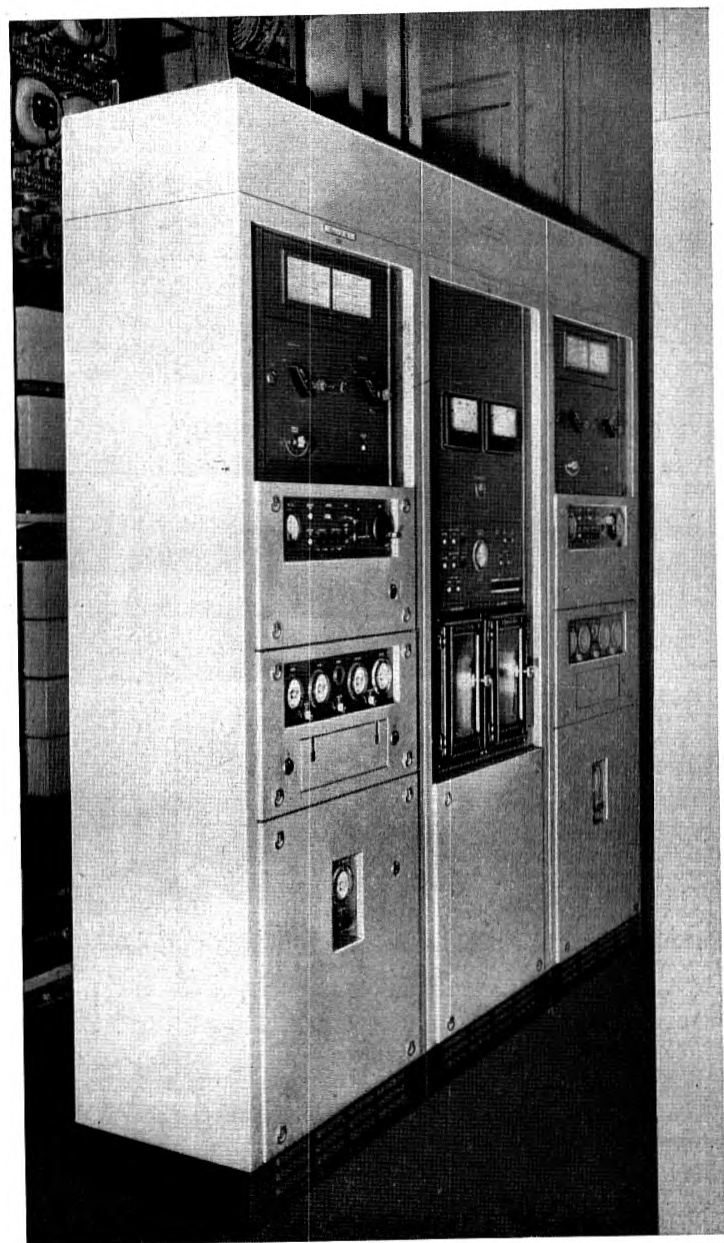
The power for the repeaters is supplied over the cable conductor from Key West. A positive potential of about 250 volts is applied to one cable and −250 volts to the other, with a loop connection between the two cables at Havana to complete the d-c. circuit. This neutral point is also connected to ground. The current in the cable conductors is at present maintained at 0.23 ampere. A view of the rectifying and control equipment for one of the polarities is given in Fig. 13. Precautions are taken against interruption of the power supply to the cable, and sensitive controls are provided to maintain the current constant in spite of earth currents and to guard against excessive currents or potentials in the cable system in case of trouble in the power supply or in the cable itself.
Laying the Cables
The laying of the cables was completed without undue incident by the Cable Ship LORD KELVIN. The task was one of unusual difficulty since modifications had to be made in the cable laying gear, some of them untried, and it was particularly desirable that the prescribed lengths and courses be realized.
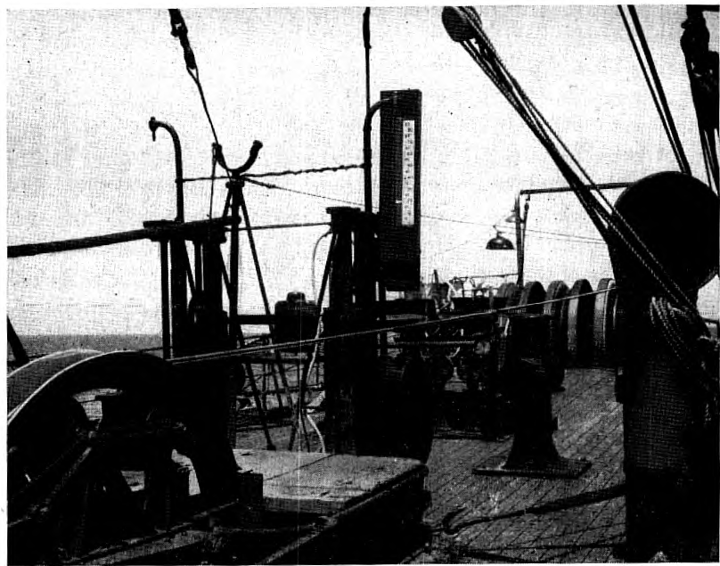
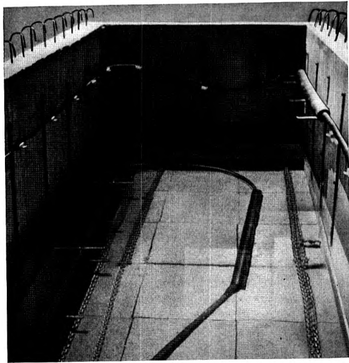
Modifications were made in the cable laying gear in order to obtain an additional margin of safety in laying repeaters. As was previously indicated, the repeater is capable of bending without harm on a diameter of approximately 72 inches; and the existing cable drum, approximately 68 inches in diameter, would have been adequate. It was felt desirable, however, to build the drum on the LORD KELVIN out to an 85-inch diameter to match the diameter of the bow sheaves. The dynamometer sheaves and the sheave leading the cable off from the brake drum presented more of a problem. The lead off sheave was replaced by a ring sheave, 85 inches in diameter, supported on wheel bearings. The frame supporting these bearings was hinged at one end and the pressure on the other end of the frame, due to the tension of the cable passing over the sheave, offered a ready means for measuring this tension. For this purpose a resistance pressure cell was employed with a recorder, which not only gave a continuous record of tension but also relayed the signals to a vertical indicator on deck for the guidance of the brake operator, and to a smaller indicator on the bridge. This arrangement is shown in Fig. 14. It is felt that it has much to recommend it over the conventional dynamometer from the standpoints of sensitivity and quickness of response.
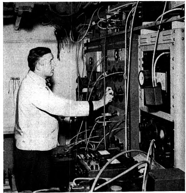
It was important to measure the transmission characteristics of the repeatered p. 84 p. 85 cable before, during and after laying, and the special equipment needed for this purpose was more than could be contained in the electrician's room usually provided on cable ships. The jointers' store room was accordingly taken over and converted into an electrical laboratory, shown in Fig. 15.
The cable, loaded on board the LORD KELVIN, with the deep sea repeaters spliced in and stowed away in the tanks, arrived off Key West on April 21, 1950. Courses had been laid out for the two cables with the idea of keeping five-mile separation between the two most of the way, and five-mile separation from the nearest of the cables that constitute the rather complicated network between Key West and Havana. It is hoped thereby to avoid having the new cables picked up by mistake in connection with the repair of other cables and to avoid confusing the two cables in case either one of them is in need of repairs.
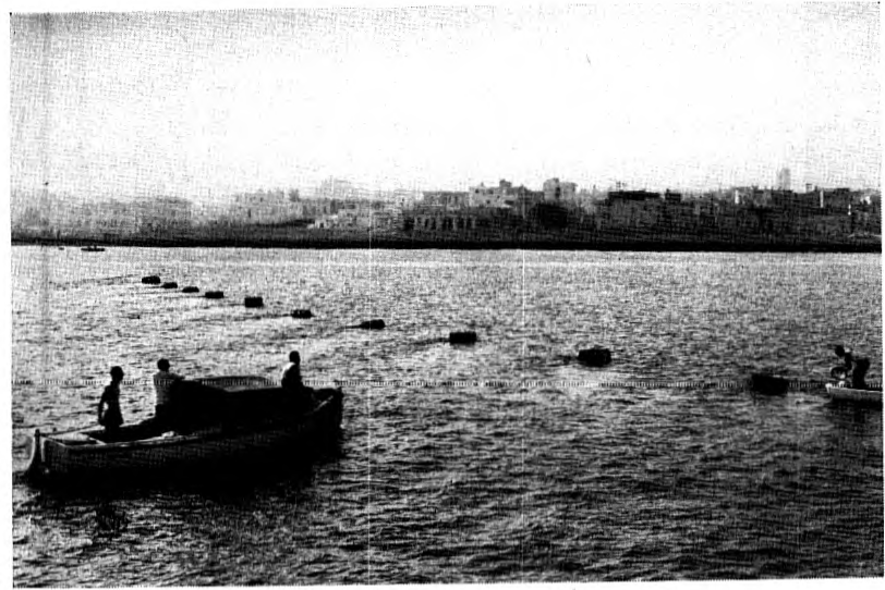
The stretch of water between Key West and Sand Key Light, a distance of about 8 n.m., is too shallow for the operation of a ship of the size of the LORD KELVIN so the sections of the two cables in this area had been laid from barges by the Long Lines Department of the American Telephone and and Telegraph Company. At Havana a new landing place had been selected. Experience with existing cables which land in Havana Harbor indicate that considerable deterioration of armor takes place in this locality and there is also the anchor menace. In addition, closeness to an existing carrier frequency cable might have given rise to undesirable crosstalk. The new landing place at the foot of B Street in Havana is about three miles from the harbor. Figure 16 shows the landing site as viewed from the cable ship during the laying operation. A view of the interior of the vault on the Havana shore is given in Fig. 17.
After putting out mark buoys at strategic points and at intervals of about 12 n.m. along the course of the cable, the Key West shore end of No. 5 cable was picked up at Sand Key and spliced on to the cable in the tanks. Then 32 n.m. of this cable were paid out, and the end buoyed at the point of final splice. The ship then proceeded to Havana, and landed the manhole repeater which was spliced to the underground cable to the office. The ship then floated the end of the cable ashore on barrels with the aid of a line operated by a winch manned by Cuban Telephone Company personnel. As soon as the end reached shore it was spliced to the repeater, the barrels were cut off, the cable dropped to the bottom and the cable on shipboard was paid out until the point of final splice was reached, where the end on board was spliced to the previously buoyed end to complete the connection between Key West and Havana.
The ship then returned to Havana, landed the end of No. 6 cable by means p. 86 p. 87 of barrels and winch line and paid out cable to the point of final splice, which in this case was about four miles from Sand Key. The end of No. 6 at Sand Key was then picked up, a repeater spliced to it and to the end of the cable in the tank, and the latter was paid out to the point of final splice. Within a short time after completing this splice, insulation measurements had been completed on the two cables, the power supply was connected in to activate the repeaters, and conversation over the cable system took place.
Careful attention was given to the amount of slack paid out, that is the excess of cable length over the actual distance traversed. This latter distance is usually determined by observing the length of a taut wire paid out continuously during the laying. In the absence of taut wire gear other methods had to be devised. Observations on buoys by radar and range finder provided almost continuous information regarding the position of the ship and gave satisfactory information on slack. The conditions for cable laying between Key West and Havana are far from good. The Gulf Stream is swift and erratic. The velocity of the current at any particular point as indicated by the stream at the buoys was found to vary considerably over a fairly short period of time. As an indication of the degree of precision obtained by careful navigation of the ship, the final results show that in each of the cables the specified length was missed by only .2 n.m., which is quite an unusual achievement.
Acknowledgment is made to the Western Union Telegraph Company, the owners of the LORD KELVIN, for their cooperation in providing the special equipment for the ship and to the Captain of the LORD KELVIN, his staff and crew, for the very satisfactory performance of the laying operation.
Since the installation of the new system, it has been subjected to comprehensive tests involving measurement of noise and intermodulation between channels as well as precise measurements at numerous frequencies of net loss of the repeatered cables at intervals of time. The system has proved to be very stable and has met the requirements laid down for it. This was as expected. Nothing unfavorable to the submerged repeater has made itself felt; but, in accordance with conservative submarine cable tradition, its performance will be critically observed over a period of time.
Activity in the development of the repeatered cable and the conduct of the Key West-Havana project centered in a small group of Bell Telephone Laboratories' engineers specializing in submarine cable work and drawing on the advice and help of other groups of various backgrounds. At times, especially when troubles were encountered, the contributions of these groups were of tremendous importance and considerable in extent. The writer, as project engineer, takes this opportunity of acknowledging the assistance of the numerous individuals involved in the success of the undertaking.
Notes
-
W. H. Martin, G. A. Anderegg, B. W. Kendall, Key West-Havana Submarine Telephone Cable System, A.I.E.E. Transactions, Vol. 41, pp. 1–19, February 1922. ↩
-
H. A. Affel, W. S. Gorton, R. W. Chesnut, New Key West-Havana Carrier Telephone Cable, B.S.T.J., Vol. 11, pp. 197–212, April 1932. ↩
-
O. E. Buckley, The Future of Transoceanic Telephony, Thirty-Third Kelvin Lecture, B.S.T.J., Vol. 21, pp. 1–19, July 1942. ↩
