The Time Factor in Telephone Transmission
Cite this paper
O. B. Blackwell, "The Time Factor in Telephone Transmission," Bell System Technical Journal, vol. 11, no. 1, January 1932, pp. 53–66.
Full text
The Time Factor in Telephone Transmission1
By O. B. BLACKWELL
Until comparatively recent years the telephone engineer gave little attention to transmission time in his problems. For all practical purposes he could assume that speech was transmitted instantly between the ends of telephone circuits. The rapid extension of the distances over which commercial telephony is given and the introduction of long telephone cables has changed the situation and has introduced time problems in telephone transmission which are of large technical interest and difficulty. As a result, time problems are receiving more consideration in the technical papers published in recent years on transmission. The accompanying bibliography lists a considerable number of such papers. There seems to be no paper, however, giving a general over-all picture of this subject. The present paper gives briefly such a picture.
THE time factor introduces five different types of problems in telephone transmission:
-
A Slowing-Down of Telephone Communication. In talking over long lengths of certain types of cable, the time interval between the formation of a sound by the speaker and its reception by the listener may become of sufficient magnitude to slow down conversation. This is not a serious matter with the types of circuits now used in the United States, even for the longest distances between points in this country. It does, however, become of considerable importance when we consider the joining together of long lengths of cable in this country and long lengths in Europe with possibly long lengths of intervening submarine cable.
-
Delay Distortion. Difference in the speed of transmission over a circuit of the different frequencies which make up speech. This may introduce peculiar distortions in speech which cause considerable interference.
-
Echo Effects. These arise from the fact that parts of the energy transmitted over a circuit may be reflected back from points of irregularity in it, particularly at the ends. Small amounts of the energy may wander back and forth over a circuit two or more times. While these echoes may affect both the talker and listener, they generally have the greatest effect on the talker who may have an uneasy feeling that the distant party wishes to break in on the conversation.
-
Effects of Voice-Operated Devices. To overcome echoes, and p. 54 under some conditions to hold circuits stable, it has become the practise of connecting into certain types of circuits, relay devices operated by the transmitted speech currents which render inoperative transmission in the opposite direction. In some cases delay in transmission may be an advantage in the operation of such devices. In other cases it may introduce serious difficulties. Conditions may be set up in which it is difficult for one party to interrupt the other. In other cases, portions of conversations may be locked out. If the voice-operated devices are not properly adjusted or if considerable noise is present, the devices may not function properly and speech mutilation may result.
-
Fading. In radio, the well-known phenomenon of fading is due to waves arriving at the receiver over different paths, the transmission times of which are such as to cause alternate strengthening and weakening of the received signal by alternate phase agreement and opposition. While this factor is mentioned here for completeness, it will not be discussed further as it is beyond the scope of this paper to discuss the problems introduced when there is more than a single path between the sending and receiving ends of a circuit. The present paper is limited to the conditions which hold where not more than one path is involved in the transmission in each direction.
Speed of Transmission
Before considering these problems in more detail it would be well to define what is meant by the speed of transmission over a circuit. There are several speeds which may have significance according to the problem involved.
Whenever a change in applied voltage is made at one end of a circuit, some evidence of this is transmitted over the circuit to the receiving end at the speed of light. In general, however, except in radio, no sufficient action to be of use is transmitted at this speed and it is largely of theoretical importance.
The speed which the engineer generally has in mind in thinking of line transmission is the speed at which the crests or the troughs of the waves pass along the line when a single-frequency potential is continuously applied at the sending end. This usually is referred to as the speed of phase transmission in the steady state. While this usually approximates the speed in which we are interested, it may in particular cases differ considerably from it. In fact, in certain types of artificial circuits the crests and troughs of the waves travel toward rather than away from the sending end.
This speed may best be explained as follows: p. 55
Since the speed of transmission in generally different for different parts of the frequency range, for simplicity a particular narrow frequency range, say between the frequencies and , is considered. It is supposed that electrical filters are applied to the circuit limiting the frequencies over it to approximately this range. If then, a voltage having a frequency, say at midpoint of this narrow range, is applied to the circuit for a short interval and then removed, the speed at which the disturbance thus set up travels down the circuit is the speed in which we are interested. A spurt of energy of this type is evidently similar to that which takes place in carrier telegraph systems when a dot impulse is applied to the circuit. This speed can be looked at, therefore, as that of carrier telegraph signals so formed.
The speeds on this basis of a number of standard constructions which represent good engineering practise today are approximately as follows:
| Type of circuit | Approximate speed in miles per second |
|---|---|
| Cable circuits loaded with 88-mh. coils at 3,000-ft. spacing | 10,000 |
| Cable circuits loaded with 44-mh. coils at 6,000-ft. spacing | 20,000 |
| Cable pairs of non-loaded 16 B. & S. gage | 130,000 |
| Non-loaded open-wire pairs | 180,000 |
| Radio | 186,000 |
Causes of Time Lag in Transmission
A pair of wires of zero resistance in free space separated from all other conductors and without leakage would transmit electrical waves over it at the speed of light. It will be noted from the above table that non-loaded open wires transmit at a speed not differing widely from this. What retardation exists comes largely from the glass insulators which cause an increase in capacity and the resistance of the wires, which causes an effective increase in inductance.
In cable circuits there is still further retardation by the increase in the capacity between the wires because of the necessity of using a certain amount of solid dielectric and particularly from the increase in the inductance of the wires when loading coils are inserted in them to decrease attenuation.
In actual circuits there is still some further retardation by the apparatus which is necessarily inserted at the terminals and at intermediate points along the circuit. The figures given in the above table are for the bare circuits. The delays caused by apparatus will, in general, reduce these speeds from 10 to 25 per cent.
Slowing-Down of Telephone Conversation
Considering the first of the above factors, it is noted that so long as the speaker at one end of a telephone circuit continues to talk, the p. 56
listener at the other end will hear the speech in proper time relation, independent of how much absolute delay there is in going from one end of the circuit to the other. However, when the speaker asks a question and waits for the answer, the slowing-down effect on his conversation will evidently be the time of transmission of his question to the distant end and the transmission back from the distant end of the answer. Considering the speed shown in the table, however, consideration may be taken of the fact that the non-loaded constructions, both open wire and cable, and the radio, are of such high speed that conversations could be carried on over them for the longest distance between places in the world without appreciable difficulty. This, however, is not the case for the loaded construction. Assume, for example, that a length of 4,000 miles would cover the wire line distance between any two points in this country. For the slowest construction noted, an interval of 0.8 second is required for transmission to the distant end and return. While it is possible to carry on conversation over a circuit with this delay, it is larger than is considered desirable. The faster of the loaded constructions shown would give a delay over circuits of this length which represents somewhere about the limit of what, at the present time, is considered satisfactory. Incidentally, the slowest of the constructions shown, for this and other reasons, is not proposed for use except for comparatively short distances.
Communication engineers must look forward to the time when the longest cable distances in North America are connected, in some cases by submarine cable, to long lengths of cable in Europe. With this as an ultimate objective, this matter of the direct effect of delay on conversation has become of considerable interest.
An appreciation of the transmission time on long telephone circuits may perhaps be gained by considering the distance required to produce an equivalent delay of sound waves traveling in air. For example, it takes about as long for a radio wave to travel half way around the earth at the equator as it does for a sound wave to travel from one speaker to another when the distance separating them is about 75 ft. Incidentally, the time required for a radio wave to travel from the earth to the planet Mars would be from about 3 to 20 minutes, assuming that it got there at all. Evidently if we have neighbors on Mars we can never hope to carry on conversation with them.
Telephone engineers have devoted considerable attention to the effects of delay on the telephone users in an effort to determine how far the electrical waves should be permitted to travel over different types of circuits. Since the present constructions do not offer any particular difficulties, for the distances now in use, a look into the future p. 57 has been taken by means of artificial delay circuits. One method has been to loop back and forth loaded conductors in a cable until the desired delay was obtained. Another method has been to record the talkers' waves on a phonograph and pick up the impressions with a second needle, displaced the desired amount from the first so as to introduce delay into the conversation.
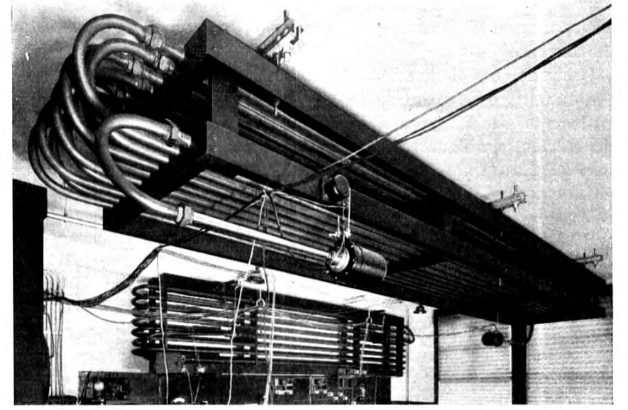
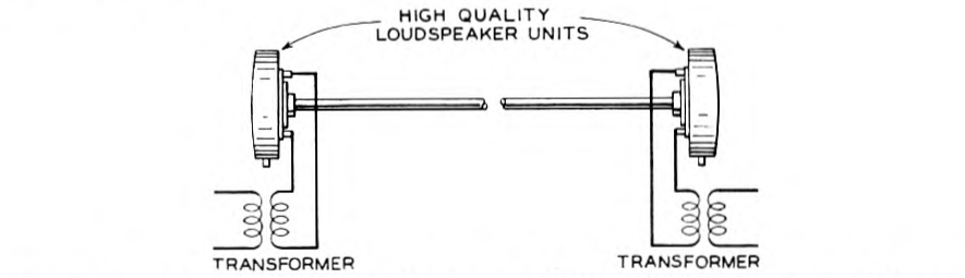
Considerable use has also been made of pipes or "acoustic" delay circuits. Fig. 1 shows an illustration of a brass pipe delay circuit used in experimental work. Fig. 2 shows the circuit in schematic form. In addition to the pipe, which is looped back and forth to conserve space, the circuit involves telephone receivers at the two p. 58 ends. The one at the sending end converts electrical energy into sound which is transmitted through the pipe and the one at the receiving end converts the sound waves back into electrical energy. The pipes are quite suitable because they have approximately the same delay at all frequencies. Various devices are required to reduce the reflections which occur at the junction of the pipe and the receiver and to equalize the attenuation.
Using devices of this nature, experimenters have found it possible to talk fairly conveniently over circuits representing time intervals as great as 0.7 second in each direction. So great delays would be considered undesirable for commercial use, however. Delays of about a third of this, in general, are considered about the maximum which is satisfactory.
Delay Distortion
In designing circuits which are electrically long, care must be exercised to insure that the transmission times for all frequencies in the transmission range are sufficiently alike to avoid objectionable transient phenomena. These effects may occur in one-way circuits as well as in two-way circuits and are not related to echo effects.
The appearance of these transients to the listener depends on whether the excess delay is at low frequencies or at high frequencies. It is rather difficult to describe the characteristic sound of a circuit with low-frequency delay. A high-frequency delay, if it is in an extreme form, sounds as though a high-pitched reed, such as a harmonica reed, was being plucked whenever there is a sudden transition in the voice sounds being transmitted over the circuit.
The characteristic effects of transients are conveniently described by the aid of oscillograms of spurts of alternating current taken before and after being sent over circuits having various delay characteristics. To begin with, it must be recalled that when any wave shape is applied to a circuit, the transmitted wave in the circuit can be expressed as the sum of the series of sinusoidal waves whose frequencies range from very low to very high values.
In the case where a sinusoidal wave of frequency is suddenly applied to the sending end of the line, the effect may therefore be explained as due to an infinity of sinusoidal waves so proportioned and phased as to add up to zero, up to the instant of application of the wave, and to equal the steady-state value of the wave at that instant. Of these waves, the most important have frequencies close to . They are propagated over the line individually with a velocity corresponding to the frequency. If the velocity of the line is the same for all p. 59 frequencies, they will evidently add up to give the same over-all wave shape at the receiving end of the line as at the sending end.
If, on the other hand, the velocity is not the same for all frequencies, there will be more or less distortion and transients in establishing the wave, though ultimately the pure wave of frequency will be established. Several oscillograms will be shown to indicate transient effects which are experienced under various conditions.
Fig. 3 is an oscillogram showing a spurt of 1,600-cycle current as applied to and received from a loaded circuit having fairly large delays in the upper part of the transmitted range compared to the delay at lower frequencies. Remembering the nature of the oscillations at the beginning and end of the applied spurt, it will be observed that the current at the receiving end consists at first of a fairly low frequency which builds up in frequency and magnitude to the steady-state value. At the end of the spurt the same transient is experienced, but in this case the higher frequency currents which have been delayed in the line are at the tail end of the train.
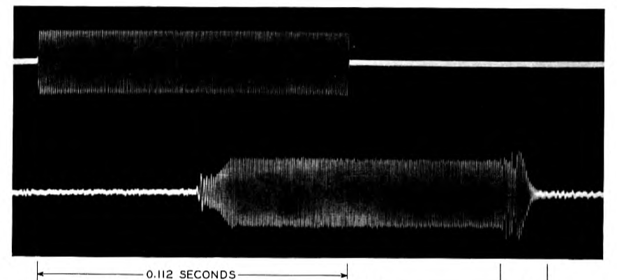
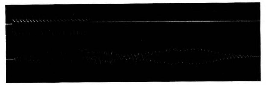
Fig. 4 shows a 200-cycle current with many harmonics of higher degree transmitted over a circuit having large delay at low frequencies. It will be noted that these high or harmonic frequencies are received in advance of the 200-cycle wave. This is because the 200-cycle wave is subject to appreciable delay while the higher frequencies are not. This circuit, while actually made up of artificial networks, had characteristics similar to certain types of long cable circuits for the lower part of the telephone frequency range. p. 60
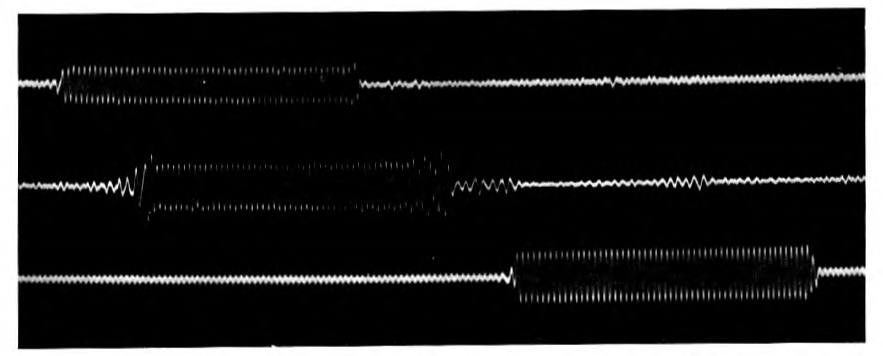
Fig. 5 shows transient effects of a 600-mile composited 19-gage H-174 side circuit. The zero lines of the three curves of this figure show slight effects of crosstalk and other interference. These effects are not, however, of sufficient magnitude to interfere with the general appearance of the signals. The upper line shows the applied 1,000-cycle current.
The next line shows the current as it was received at the end of the line. The transients which are produced at the beginning and ending of the signals are evident.
By the insertion of proper networks it is possible to correct for distortions of this kind. In the last line there is shown the received cur- rent when a delay correcting network of this kind is applied in series with the circuit. It should be noted that while the delay in the reception of the signal is somewhat increased (as shown by the displacement p. 61 of the whole signal farther to the right) the transients at the beginning and stopping of the signal are very much reduced.
Echoes
In designing telephone circuits which are electrically long, an important problem is presented by the necessity of avoiding echo effects. These are caused by reflection of electrical energy at points of discontinuity in the circuit and are very similar to echoes of sound waves in an auditorium. The reflected waves are usually considered as echoes when there is an appreciable delay with respect to direct transmission. Some of the reflected waves return to the receiver of the talker's telephone so that if the effects are severe he may hear an echo of his own words. Other reflected waves enter the receiver of the listener's telephone and, if severe, cause the listener to hear an echo following the directly received transmission.
Reflections of voice waves occur in all practical telephone circuits. It is only in telephone circuits of such length as to require a number of repeaters, however, that echo effects become serious. The fact that the circuits are electrically long makes the time lag of the echoes appreciable. At the same time, the telephone repeaters overcome the high attenuation in these long circuits and consequently make the echoes louder. The seriousness of the effect is a function of both the time lag and the volume of the echo relative to the direct transmission, becoming greater when these are increased.
In telephone circuits the most important points of discontinuity are usually the two ends of the circuit. In a four-wire telephone circuit these are the only points of discontinuity.
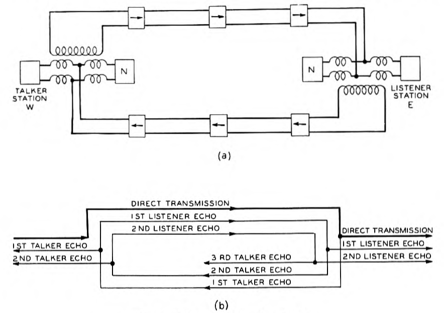
Fig. 6 shows a schematic diagram of a four-wire telephone circuit and a schematic representation of the direct transmission over the circuit, together with the various talker and listener echoes which are set up. The rectangles at the extreme right and left are intended to represent the telephone sets used by two subscribers at the west and east terminals of the circuit. The rectangles marked represent electrical networks which simulate or balance more or less perfectly the impedance of the telephone sets. In the four-wire circuit the rectangles with arrows represent one-way repeaters or amplifiers. At each terminal the two separate one-way circuits comprising the four-wire circuits are joined together by means of the familiar balanced transformers. When the subscriber at talks, the transmission passes to over the upper path in the four-wire circuit. This is indicated by the heavy line labeled "Direct Transmission" in part b of p. 62 the figure. When subscriber talks, transmission passes over the lower path in a similar manner.
Considering part b of the figure, it will be noted that when direct transmission is received at the east end of the circuit, a portion of the current passes to the opposite side of the four-wire circuit and is transmitted to the subscriber at the west end as a talker echo. Similarly, a portion of this talker echo is transmitted over the upper part of the circuit to the listener at the east end of the circuit as a listener echo. Successive talker and listener echoes follow this, as indicated in the diagram. If the networks at the two ends of the circuit can be made to simulate accurately the subscriber circuits, none of these echoes will exist. A high degree of simulation, however, is impracticable in an economical telephone plant under usual conditions. In two-wire circuits with many repeaters the echo paths may become very complicated.
An interesting case of "echoes" is that which may be produced when two radio stations are sending out the same program at the same wavelength. The program as received by one of these stations over wire circuits is, of course, slightly delayed with respect to a station nearer the source of the program. It is possible, then, for a receiving set properly located to receive both of these stations, in which case if p. 63 the time difference is sufficient one of them will sound like an echo of the other. In this case there may be the added peculiarity that if the weaker station is the one at which the program is received first it will appear that the "echo" is in advance of rather than following the sound which appears to cause it.
Time Effects with Voice-Operated Devices
Switching devices operated by the voice currents themselves are frequently introduced into long telephone circuits. In general, the effect of such devices is to render inoperative transmission in the direction opposite to that of the speech waves which are going over a circuit at the particular instant. The first use of any considerable importance to which such devices were put was in connection with long circuits for the purpose of preventing the building-up of undesirable echoes. More recently, however, long radio telephone circuits have come into use. These circuits may vary rapidly in transmission effectiveness. If these circuits are arranged to be operative in both directions at a time it would be very difficult to prevent their becoming unstable and possibly setting up oscillations. For this reason such circuits are frequently operated with switching arrangements such that the circuits leading to both transmitting stations are normally disabled and rendered inoperative. When a subscriber speaks at either end, therefore, the voice currents must operate switching devices which restore the circuits leading to his transmitting station. Incidentally, this must render inoperative the receiving circuit at the same time.
A very interesting application of time delay has been made in connection with radio systems so operated. In this arrangement the voice currents when they reach the disabling point are passed through an artificial line in which a desired amount of delay is incorporated. Just before entering this line a fraction of the energy is taken, rectified, and made to operate the switching mechanism for restoring the circuit to operating condition. This switching is so arranged as to be completed by the time that the voice currents have passed through the artificial delay circuit and are ready to proceed down the line. If it were not for this arrangement a small part of the speech currents might be dissipated during the interval while the switching mechanisms were operating.
Fig. 7 is similar to Fig. 6 noted above with the exception that the application of an echo suppressor is shown.
When the subscriber at the left of the drawing begins to talk, the waves set up in his telephone are transmitted over the upper part of the circuit. Upon reaching the input of the echo suppressor, a small p. 64 part of the energy is diverted to short circuit the lower branch of the circuit, as indicated. Meanwhile, the main transmission passes on to the subscriber at the right. Echoes which return in the lower part of the circuit are blocked as indicated. After the talker has ceased speaking, the device remains operative for a time equal to the delay of the echo as measured from the input of the device to the disabling point plus an additional time to take care of echoes in the circuit between the four-wire terminal and the subscriber.
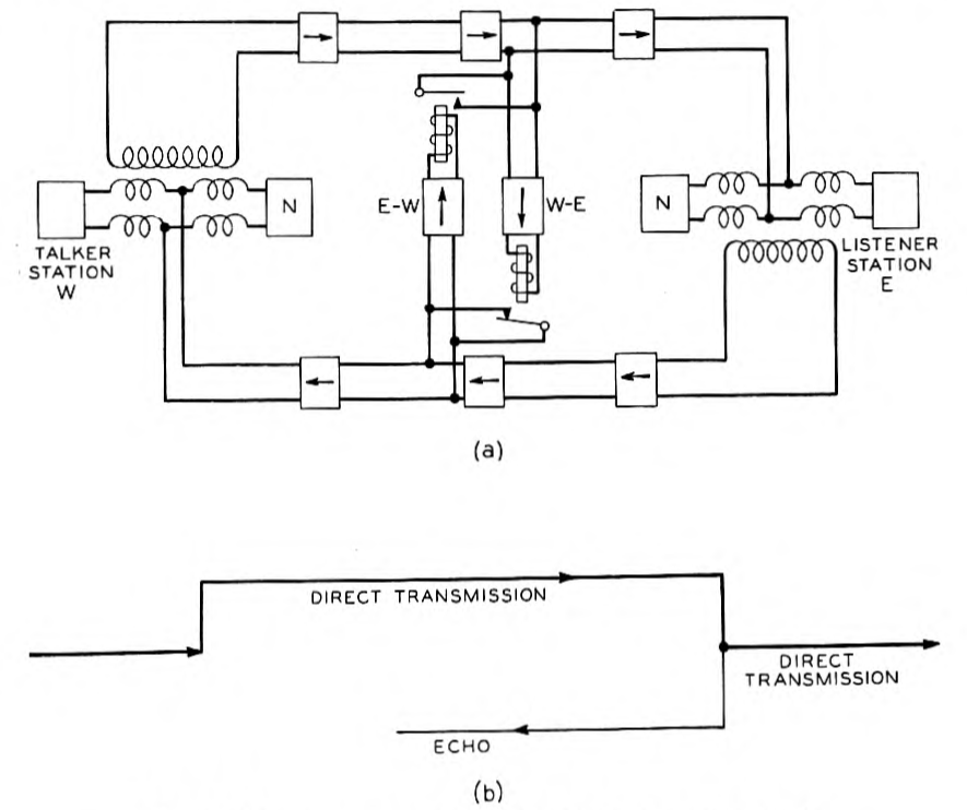
When the suppressor releases, the circuit is again free to transmit in either direction. When the right-hand subscriber talks, the action is similar except that the other half of the echo suppressor operates.
In practical use the echo suppressors are so carefully controlled that telephone users are generally unable to tell whether a suppressor is on the circuit or not. This is due to the short delays and careful adjustments of the time functions of the device. It is possible, however, if the delays are longer and the adjustments are made with less care, to introduce two types of difficulty. If one subscriber talks fairly steadily p. 65 he may hold the suppressor operative so continuously that it is difficult for the other party to break in on the conversation if he so desires. If one subscriber started to reply almost simultaneously with the termination of the other's speech, part of his reply might be blocked at the echo suppressor along with the last of the echo.
Further difficulties arise if two circuits, each containing an echo suppressor of this kind, are switched together in tandem. In this case it would be possible for the subscribers to completely block each other's speech if they started talking simultaneously.
In the case of radio circuits operated as noted above, difficulties are introduced somewhat similar to that of two echo suppressors in tandem.
The above will sufficiently suggest the types of difficulties which arise from delay in connection with voice-operated devices. Certain of the papers in the accompanying bibliography consider these problems in more detail.
In preparing the accompanying bibliography, no attempt has been made to make it complete. It is believed, however, to contain most of the important publications on the subject.
Bibliography
General
"Telephone Transmission over Long Cable Circuits," A. B. Clark. Bell System Technical Journal, vol. 2, no. 1, Jan. 1923, p. 67–94; A. I. E. E. Trans., vol. 42, Feb. 1923, p. 86–96; Electrical Communication, vol. 1, no. 3, Feb. 1923, p. 26–40.
"Development and Application of Loading for Telephone Circuits," Thomas Shaw and William Fondiller. A. I. E. E. Trans., vol. 45, Feb. 1926, p. 268–292; Bell System Technical Journal, vol. 5, no. 2, April 1926, p. 221–281; Electrical Communication, vol. 4, no. 4, April 1926, p. 258–276, and vol. 5, no. 1, July 1926, p. 38–53.
"Extending the Range of Loaded Lines by Echo Suppression and Phase Equalization," K. Küpfmüller. Elektrische Nachrichten-Technik, vol. 3, no. 3, Mar. 1926, p. 82–88.
"Transmission Characteristics of Long Distance Telephone Cable Connections," K. Küpfmüller. Europäischer Fernsprechdienst, no. 5, July 1927, p. 19–33.
"Telephone Communication System of the United States," Bancroft Gherardi and F. B. Jewett. Bell System Technical Journal, vol. 9, no. 1, Jan. 1930, p. 1–100.
"Recent Developments in Toll Telephone Service," W. H. Harrison. A. I. E. E. Trans., vol. 49, no. 1, Jan. 1930, p. 166–176.
"Some Recent Developments in Long Distance Cables in the United States of America," A. B. Clark. Bell System Technical Journal, vol. 9, no. 3, July 1930, p. 487–492.
"Transmission Characteristics of Open-Wire Telephone Lines," E. I. Green. Bell System Technical Journal, vol. 9, no. 4, Oct. 1930, p. 730–759.
"Range and Economy of the Toll Cable Lines of System II of the C. C. I.," K. Höpfner and F. Lüschen. Europäischer Fernsprechdienst, no. 21, Jan. 1931, p. 3–16.
Delay Distortion
"Theory of the Transient Oscillations of Electrical Networks and Transmission Systems," J. R. Carson. A. I. E. E. Trans., vol. 38, pt. 1, 1919, p. 345–427.
"Transient Phenomena in Wave Filters," K. Küpfmüller. Elektrische Nachrichten-Technik, vol. 1, no. 5, Nov. 1924, p. 141–152.
"Measurement of Phase Distortion," Harry Nyquist and Smart Brand. Bell System Technical Journal, vol. 9, no. 3, July 1930, p. 522–549.
"Building-Up of Sinusoidal Currents in Long Periodically Loaded Lines," J. R. Carson. Bell System Technical Journal, vol. 3, no. 4, Oct. 1924, p. 558–566.
"Attenuation of Band-Pass Filters in the Transmission Range," H. F. Mayer. Elektrische Nachrichten-Technik, vol. 2, no. 10, Oct. 1925, p. 335–338.
"Phase Distortion and Phase Distortion Correction," S. P. Mead. Bell System Technical Journal, vol. 7, no. 2, April 1928, p. 195–224.
"Distortion Correction in Electrical Circuits with Constant Resistance Recurrent Networks," O. J. Zobel. Bell System Technical Journal, vol. 7, no. 3, July 1928, p. 438–534.
"Effects of Phase Distortion on Telephone Quality," J. C. Steinberg. Bell System Technical Journal, vol. 9, no. 3, July 1930, p. 550–566.
"Phase Distortion in Telephone Apparatus," C. E. Lane. Bell System Technical Journal, vol. 9, no. 3, July 1930, p. 493–521.
Echoes
"Irregularities in Loaded Telephone Circuits," George Crisson. Bell System Technical Journal, vol. 4, no. 4, Oct. 1925, p. 561–585; Electrical Communication, vol. 4, no. 2, Oct. 1925, p. 98–110.
"Limitation of the Gain of Two-Way Telephone Repeaters by Impedance Irregularities," George Crisson. Bell System Technical Journal, vol. 4, no. 1, Jan. 1925, p. 15–25.
"Connecting-Together of Four-Wire Lines," K. Höpfner. Telegraphen- und Fernsprech-Technik, vol. 16, no. 6, June 1927, p. 166–169.
"Measurement of Echo Attenuation," R. Feldtkeller and H. Jacoby. Telegraphen- und Fernsprech-Technik, vol. 17, no. 3, March 1928, p. 61–71.
Voice-Operated Devices
"Echo Suppressors for Long Telephone Circuits," A. B. Clark and R. C. Mathes. A. I. E. E. Trans., vol. 44, April 1925, p. 481–489; Electrical Communication, vol. 4, no. 1, July 1925, p. 40–50.
"Echo Suppressors for Telephone Lines," H. F. Mayer and H. Nottebrock. Telegraphen- und Fernsprech-Technik, vol. 15, no. 11, Nov. 1926, p. 353–355.
"New York-London Telephone Circuit," S. B. Wright and H. C. Silent. Bell System Technical Journal, vol. 6, no. 4, Oct. 1927, p. 736–749.
"Transatlantic Telephony. The Post Office Differential Voice-Operated Anti-Singing Equipment," C. A. Beer and G. T. Evans. P. O. E. E. Journal, vol. 20, no. 1, April 1927, p. 65–72.
"Bridge for Measuring Small Time Intervals," Joseph Herman. Bell System Technical Journal, vol. 7, no. 2, April 1928, p. 343–349.
"New Standard Echo Suppressor," W. F. Marriage, P. R. Thomas, and K. G. Hodgson. Electrical Communication, vol. 9, no. 3, Jan. 1931, p. 196–202.
Related Transmission
"Transmission of Pictures over Telephone Lines," H. E. Ives, J. W. Horton, R. D. Parker, and A. B. Clark. Bell System Technical Journal, vol. 4, no. 2, April 1925, p. 187–214.
"Some Studies in Radio Broadcast Transmission," Ralph Bown, DeL. K. Martin, and R. K. Potter. Bell System Technical Journal, vol. 5, no. 1, Jan. 1926, p. 143–213.
"Wire Transmission System for Television," D. K. Gannett and E. I. Green. Bell System Technical Journal, vol. 6, no. 4, Oct. 1927, p. 616–632.
"Some Developments in Common Frequency Broadcasting," G. D. Gillett. Proceedings of the Institute of Radio Engineers, vol. 19, no. 8, Aug. 1931, p. 1347–1369.
Notes
-
Presented at the South West District Meeting of the A. I. E. E., Kansas City, Mo., October 22–24, 1931. ↩
