A New Key West—Havana Carrier Telephone Cable
Cite this paper
H. A. Affel, W. S. Gorton and R. W. Chesnut, "A New Key West—Havana Carrier Telephone Cable," Bell System Technical Journal, vol. 11, no. 2, April 1932, pp. 197–212.
Full text
The Bell System Technical Journal
April, 1932
A New Key West—Havana Carrier Telephone Cable1
H. A. AFFEL, W. S. GORTON and R. W. CHESNUT
A new submarine cable has recently been laid between Key West and Havana in order to furnish more telephone facilities between the United States and Cuba. The cable has a single central conductor with concentric tape return and employs the newly developed material paragutta for insulation. A carrier telephone system provides three telephone channels. As ultimately developed a still greater number of facilities may be made available over the cable.
IN January 1931, telephone service was inaugurated over a new submarine cable to Cuba, spanning the hundred-mile or more stretch of deep water between Key West and Havana. Telephone service to Cuba dates back about 10 years earlier when three continuously loaded cables were laid between Key West and Havana. These cables and their associated terminal apparatus were completely described in a paper2 by Martin, Anderegg, and Kendall, presented to the Institute at its midwinter convention in 1922. The new cable, like the earlier ones, is owned by the Cuban-American Telephone and Telegraph Company, an organization controlled jointly by the American Telephone and Telegraph Company and the Cuban Telephone Company for the purpose of providing telephone facilities between the United States and Cuba.
In the past decade the communication art has advanced in many respects so that three telephone circuits are provided by carrier operation, using high frequencies, over this single improved type cable which is not much larger than one of the three earlier cables.
The three telephone channels now made available are connected to carrier telephone channels operating on open-wire lines northward to Washington and thence over four-wire cable circuits to New York where they terminate as New York-Havana circuits. The telephone circuits derived from the three older cables now terminate at Miami or Key West, where they may be switched to other distant points.
The new cable was designed to satisfy economically the initial need p. 198 for more circuits by an adaptation of standard carrier apparatus. The design was made sufficiently liberal so that when still more facilities are required certain further development work should make it possible to obtain them over the same cable. From a transmission standpoint, the feature of most interest is the unusually low receiving levels at which operation is successfully carried on.
The Cable
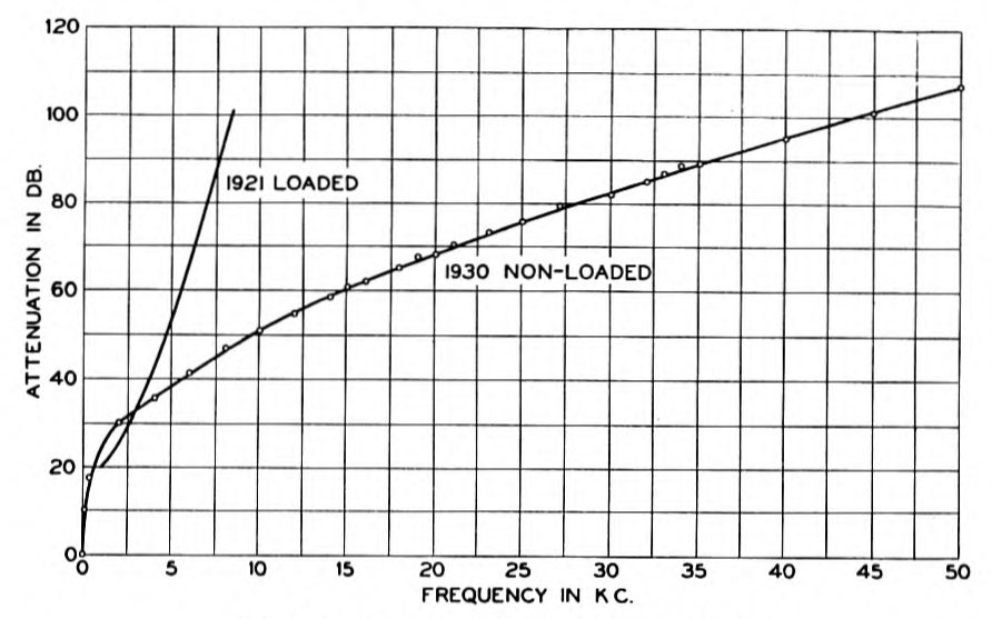
The new cable, which has been designated the 1930 cable, is the longest deep sea telephone cable in existence and is also unique in being the longest, telephone cable circuit without intermediate repeaters and without inductive loading. It is somewhat longer (3.7 nautical miles3) than the longest of the 1921 cables and is operated over a far wider frequency range. The new cable operates at frequencies up to about 28,000 cycles per second, and can operate up to a still higher frequency, whereas the old cables are operated only up to 3,800 cycles per second. The longest deep sea carrier frequency cable before the laying of the present cable was that connecting Tenerife with Gran Canaria in the Canary Islands. This cable4 is non-loaded and is intended to utilize approximately the frequency range now utilized by the new cable but is much shorter, being only 39.7 nautical miles in length.
Paragutta
The feature of the new cable which has enabled this great improvement to be attained is the insulation, which is of paragutta. This material was developed at the Bell Telephone Laboratories and is composed of deproteinized rubber, deresinated balata, and wax. It has been described in detail by A. R. Kemp.5 Heretofore submarine cables having waterproof insulation, with the exception of the Catalina Island cables6 which are insulated with a special rubber mixture, have almost invariably been insulated with gutta percha, or balata, or a mixture of these substances. Paragutta has better electrical properties than any of these materials.
Some idea of the improvement represented by paragutta can be had from Table I which lists the significant a-c. electrical properties p. 199 of representative submarine cable insulations. It is evident from these figures that the use of paragutta effects a considerable reduction in the size of a cable for a given attenuation, not only for telephone cables but also for telegraph cables. This decrease in size is due both to the smaller dielectric constant and to the smaller leakance.7 The smaller dielectric constant is equally effective in reducing the size of both loaded and non-loaded cables. The smaller leakance is especially important in the case of loaded cables. The decrease in size due to the use of paragutta varies, of course, with the size of the cable. Some idea of its amount may be obtained from the fact that a cable insulated with gutta percha of the sort used in the 1921 cables would weigh 45 per cent more and cost about 65 per cent more than the new cable,
The use of this new material in the manufacture of a cable gave rise to numerous problems, one of which deserves particular mention. namely that of jointing the paragutta. A new technique of jointing was developed which not only produces good joints in paragutta-insulated cable but also produces better joints in gutta percha-insulated cable than can be made by the conventional process which has been in general use since gutta percha cables were first manufactured.
TABLE I
Comparative Electrical Properties of Gutta Percha and Paragutta Insulations of Submarine Cables at 22 Kilocycles per Second under Sea Bottom Conditions
| Dielectric Constant | Ratio of Leakance to Capacitance | |
|---|---|---|
| Gutta Percha (telegraph cable) | 3.3 | 4040 |
| Gutta Percha as used in 1921 Key West-Havana Cables | 3.1 | — |
| Gutta Percha as used in Tenerife-Gran Canaria and Algeciras-Ceuta Telephone Cables * | 2.92 | 3815 |
| Paragutta (Key West-Havana 1930 Cable) | 2.67 | 229 |
* Electrical Communication, Vol. 9, p. 217, 1931.
Cable Design
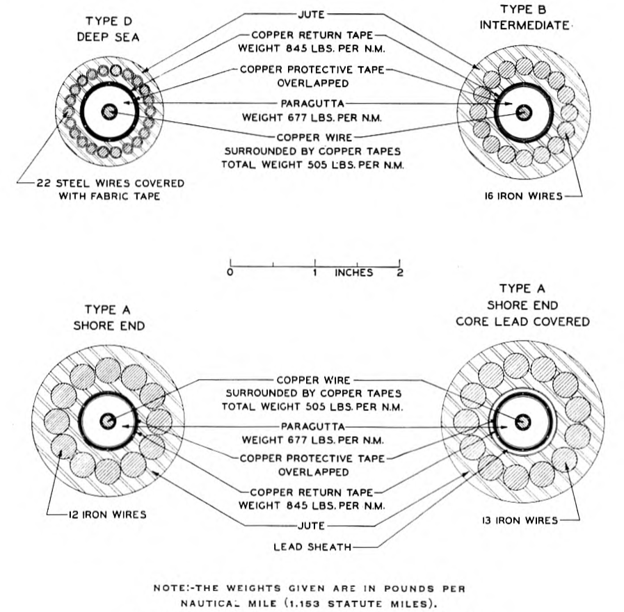
The 1930 cable is similar in type to the 1921 cables except that it is not loaded. It is provided with copper return tapes8 and also with a thin copper tape under the return tapes for protection against marine organisms. The principle of the electrical design of the cable was to strike an economic balance between all of the factors affecting the attenuation and thus to secure a cable of the desired attenuation at the lowest possible cost. The result of this procedure is a core structure having a much greater thickness9 of insulation compared p. 200 with the diameter of the central conductor than is the case with low-frequency cables, either telephone or telegraph. The particular factor contributing to this result is the large skin effect, which occurs principally in the central conductor but also appreciably in the return tapes. The ratio of the a-c. to the d-c. resistance increases at a rapid rate if the central conductor and return tapes are made heavy in an attempt to reduce the weight of the insulation. At carrier frequencies p. 201 the effect of the armor wire is negligible from the attenuation standpoint. Magnetic modulation due to the presence of the armor wire was investigated carefully and likewise found to be negligible. The lay, or pitch, of the copper return tapes was made much longer10 than was the case in the 1921 cables. This brought about a substantial decrease in the effective resistance of the tapes themselves and reduced the eddy-current losses which are due to the helical nature of the return tapes.
In all matters of mechanical design accepted cable practice was followed. A discussion of some of the mechanical features of cable design, as well as some account of the general submarine cable problem, has been given by Martin, Anderegg, and Kendall in the paper above referred to.
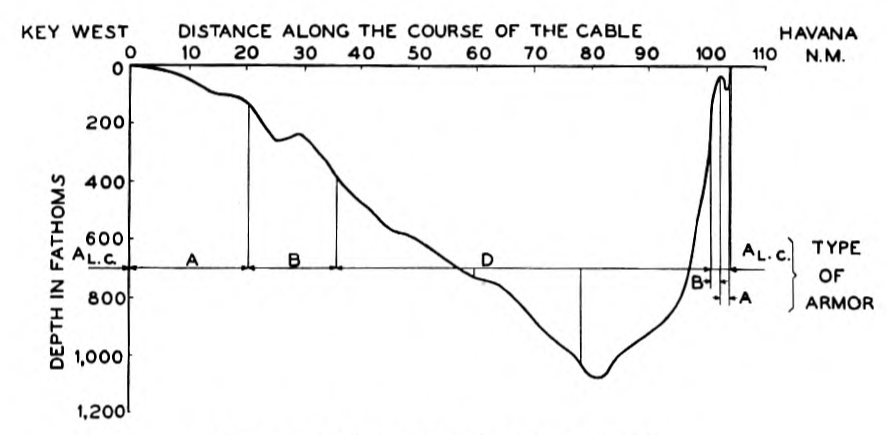
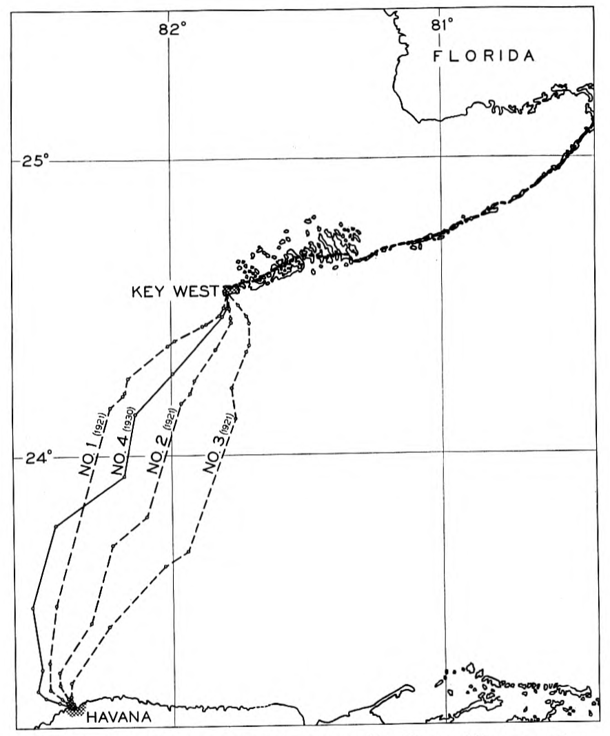
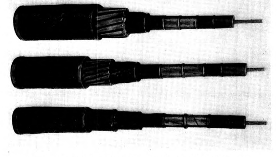
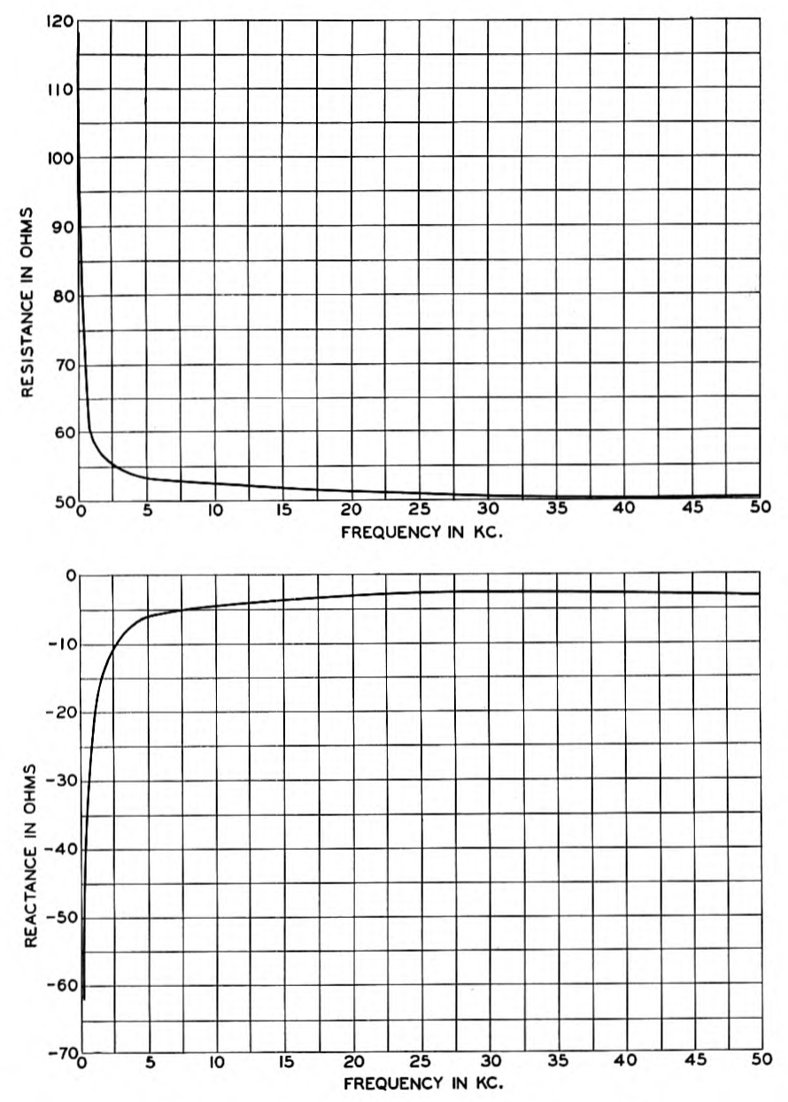
The new cable is 108.6 nautical miles (125.2 statute miles) in length. It was manufactured by the Norddeutsche Seekabelwerke-A.G. of Nordenham, Germany and laid by their cable steamer "Neptun." Its route is shown in Fig. 1, and the profile of the route in Fig. 2. The maximum depth attained is 1080 fathoms (6480 feet). The particulars of the core structure are given in Table II and those of the armor in Table III. Cross-sections of the various types of cable are shown in Fig. 3. A photograph of three of the types is shown on Fig. 4. The attenuation of the cable and its characteristic impedance are shown in Figs. 5 and 6, respectively. The attenuation is characteristic of a non-loaded cable in that it increases rapidly at low frequencies but less rapidly at high frequencies whereas the reverse is true, in a p. 202 general way, of the loaded cable. This is shown by the attenuation curve of one of the 1921 cables which is given in Fig. 5 for comparison. The d-c. properties of the laid cable are shown in Table IV.
TABLE II
Core Structure of Key West-Havana Cable No. 4
| Central Conductor | |
| Central Wire | Diameter .138 in. |
| Surrounds | 6 tapes .0142 in. × .079 in. |
| Weight of Whole | 505 lbs./n.m. |
| Diameter of Whole | .167 in. |
| Impregnating Compound | .0024 in. thick |
| Insulation | |
| Weight (Including Compound) | 677 lbs./n.m. |
| Outer Diameter | .614 in. |
| Fabric Tape | .010 in. thick |
| Protective Tape (Copper) | 1 in. × .004 in. with 10% overlap |
| Weight | 209 lbs./n.m. |
| Return Conductor | 6 tapes .319 in. × .019 in. |
| Weight | 845 lbs./n.m. |
| Outer Diameter | .681 in. |
| Ozokerite Tape | |
| Outer Diameter | .704 in. |
TABLE III
Armor for Key West-Havana Cable No. 4
| Type of Armor | Length Laid n.m. | Armor Wires: No. of Wires | Armor Wires: Diameter (Inches) | Weight of Completed Cable (lbs. per n.m.): (1) Wet | Weight of Completed Cable (lbs. per n.m.): (2) In Water | Outer Diameter of Cable (Inches) |
|---|---|---|---|---|---|---|
| Al.c. | .40 | 13 | .300 | 29300 | 21660 | 1.93 |
| A | 21.94 | 12 | .300 | 24000 | 17380 | 1.81 |
| B | 17.50 | 16 | .200 | 16140 | 11000 | 1.57 |
| D | 68.79 | 22 | .104 e.w.t. | 8990 | 5115 | 1.30 |
l.c. = lead covered.
e.w.t. = each wire taped.
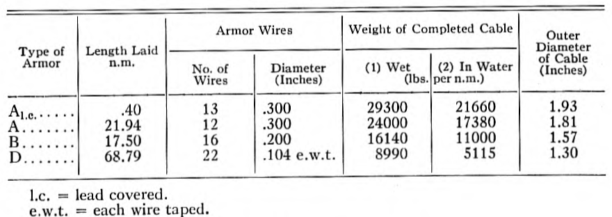
TABLE IV
Conductor Resistance, Dielectric Resistance and D-C. Capacity of Key West-Havana Cable No. 4 as Laid
| Conductor (Central) Resistance | 242 ohms |
| Dielectric Resistance | 1090 megohms |
| Capacity | 22.52 microfarads |
One respect in which the present cable differs from the 1921 cables is that it has a single-core termination instead of an unbalanced-type twin-core termination.11 Experience with the 1921 cables has shown p. 203 that there is no advantage from the standpoint of the reduction of atmospheric and other extraneous interference to be had from the use of an unbalanced twin-core termination in a cable provided with copper return tapes. A balanced twin-core termination would be effective in reducing interference but certain disadvantages would be connected with its use. Very little shielding beyond that naturally furnished by the sea water is needed and that additional amount is furnished by a wrought iron pipe enclosing the cable between the cable hut and the level of the lowest tides.
Carrier System
As noted previously, in providing carrier apparatus to make use of the high-frequency transmission properties of the new cable, an effort p. 204 was made to use existing standard types of equipment as far as possible. The three telephone channels are now obtained by an adaptation of carrier apparatus ordinarily12 used for long-distance transmission over open-wire lines.
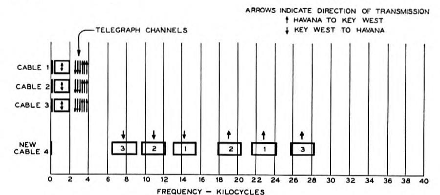
The six frequency bands (one for each direction for the three channels) are allocated as shown in Fig. 7. A d-c. telegraph channel is also indicated. This figure likewise shows the frequency allocation of the one telephone and four telegraph channels (three carrier and one direct current) now carried over each of the three older cables. It will be noted that the band width of the new telephone channels is considerably greater than that of the old ones, thus furnishing higher quality speech transmission. In addition, a considerable range of frequencies remains unused on the new cable. This range may be developed when additional message telephone, broadcasting, or telegraph facilities are needed.
In adapting the existing type carrier apparatus for operation over the new cable, the problems consisted chiefly in (a) providing for satisfactory transmission over a circuit of considerably higher attenuation than the apparatus was originally designed for and (b) providing the p. 205 necessary transformers to connect together the parts of the circuit having different impedances.
The carrier apparatus is installed in existing telephone offices at Key West and Havana. In each case the office is somewhat over one mile from the cable hut at the water's edge. The submarine cable circuit is connected to the apparatus in the offices through pairs of wires in an underground cable of the paper-insulated lead-covered type, which also carries the circuits of the older cables. In Fig. 8 are shown schematically the connections of the whole cable communication system. The arrangements are practically identical at the two terminals except for differences incident to the fact that different frequency bands are transmitted in the two directions.
Certain coils and condensers are located at the cable hut. A transformer connects the unbalanced 50-ohm submarine cable to the balanced-to-ground 130-ohm pair in the lead-covered cable. The other coils and condensers form a "composite set" which connects the submarine cable to a second pair in the lead-covered cable in order to transmit direct current. This may be used as a d-c. telegraph channel or as an insulation testing circuit.
The carrier equipment in the telephone office may be considered in two categories: (a) that which is derived from standard open-wire carrier systems as described in the paper previously referred to, and (b) that which is additional and special for this installation.
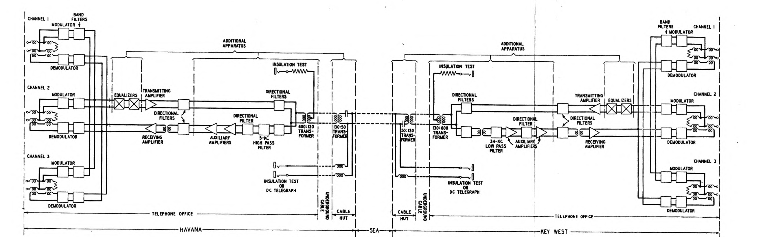
The additional equipment consists chiefly of added receiving amplifiers and directional filters to care for the greater gain and selectivity needed to operate at the higher attenuation. It includes also equalizers which correct for the varying attenuation of the cable with frequency and a transformer to connect the 600-ohm apparatus to the 130-ohm pair in the underground lead-covered cable. Also, at Key West, a 34-kc. low-pass filter was added to suppress interference from a local radio station having a frequency of about 100 kc. At Havana, a 5-kc. high-pass filter was added to suppress certain relatively low-frequency noises picked up by the circuits in the underground cable.
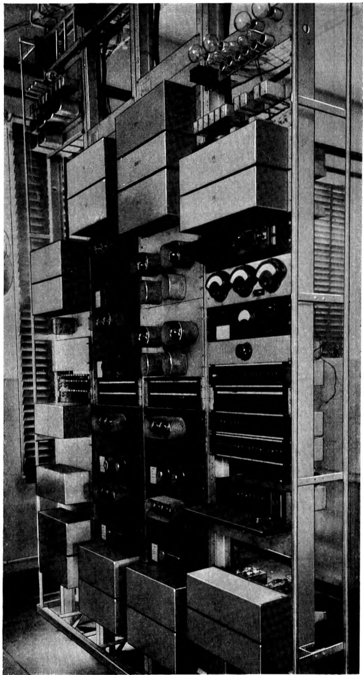
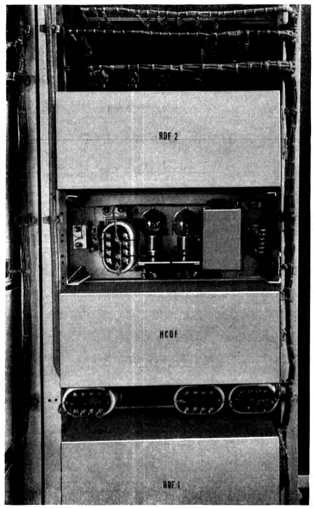
A photograph of the apparatus installed in the Key West office is shown in Fig. 9. It will be noted that this consists of four "bays" of apparatus, the three nearer of which are practically the same as the carrier equipment ordinarily supplied on long-distance telephone circuits. The fourth bay has the special amplifying and equalizing equipment previously mentioned. A rear view, Fig. 10, shows the interior of one of the special amplifiers, including certain of the special impedance-correcting transformers. Apparatus of a similar nature is installed at Havana.
Certain Transmission Problems
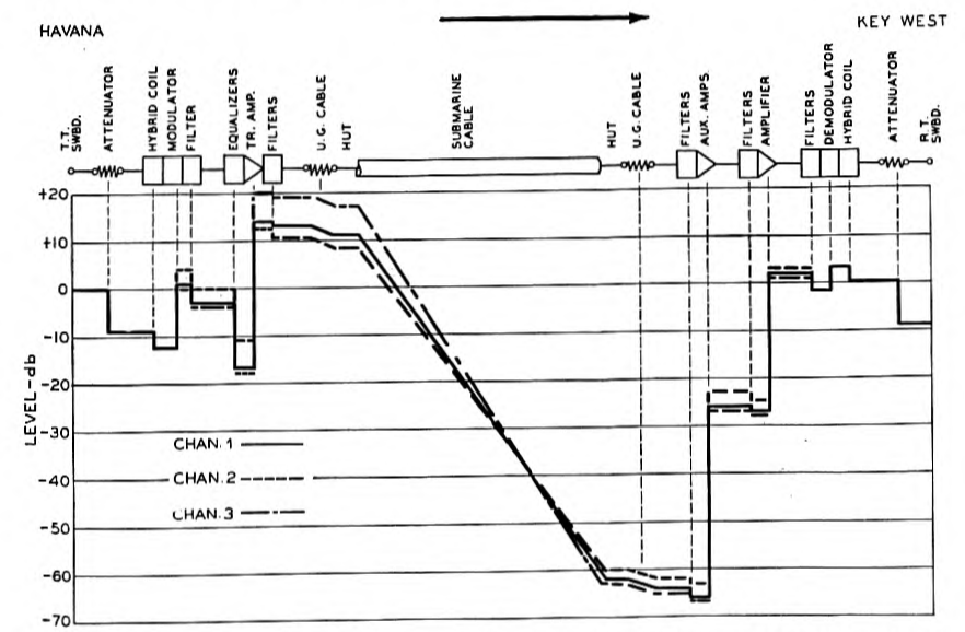
Fig. 11 shows the relative energy of the carrier-frequency speech currents as they traverse the circuit from Havana to Key West. In this direction the higher carrier frequencies are employed. Starting from the left of the diagram, the toll switchboard point, which is taken as zero level, the current of a channel suffers a loss of 9 db in a p. 208 p. 209 resistance attenuator which is introduced in the circuit to give flexibility in control. This loss can be reduced in value to improve transmission in the case of connections to distant points. As the speech currents enter the carrier apparatus they receive, in addition to the frequency change, an amplification of from 5 to 10 db in the modulator unit and from 10 to 20 db in the transmitting amplifier. The highest frequency channel receives the highest gain and leaves the common transmitting amplifier at a level about 20 db higher than at the toll switchboard.
From here the currents leave for Key West by way of the underground cable, the cable hut, and the submarine cable itself.
The highest frequency channel is attenuated somewhat over 80 db by the time it reaches the receiving apparatus at Key West. Here it is stepped up about 70 db by the amplifiers, from the output of which it suffers a few db loss in the demodulator circuit and 9 db loss in the receiving attenuator circuit. If the connection is continued to another toll office, such as Miami or New York, this attenuator is adjusted to give a 9 db loss between the hybrid coil at Key West and the receiving toll switchboard in question.
The problem of satisfactory transmission of the speech currents in this path involves several specially critical points. The transmitting amplifier must amplify to the high levels required without modulating sufficiently to produce troublesome new frequencies falling within its own group of frequency bands. New frequencies produced by the amplifier and falling outside this group are suppressed by the directional filters and cause no trouble. Additional possible sources of modulation are the directional filters and impedance matching transformers. They must transmit the high level currents coming from the amplifier but must not modulate them sufficiently to produce troublesome new frequencies falling within the oppositely directed group of bands. The latter are at an exceedingly low level and so the p. 211 modulation in these circuit elements must be kept extremely small. Some ordinary resistances, mica condensers, etc., have been found to have enough modulation to be serious. Ordinary iron core transformers are likely to be very bad. Special design was required to reduce the modulation in the impedance matching transformers to tolerable limits.
Noise Prevention
As noted previously, at the receiving end the important problem is naturally to keep the low level receiving circuit free from interference. In taking the necessary precautions along these lines, a large number of sources of noise were investigated. These included crosstalk from other carrier telephone or telegraph systems, high-frequency oscillations set up by d-c. telegraph apparatus in the vicinity, radio stations, power wires, submarine telegraph cables, and many minor sources.
Space requirements prevent a complete discussion of this work but a tabulation of a few of the remedial measures may be interesting.
Special filters in all telephone office power supply sources.
Special shielding arrangements in the construction of the receiving amplifiers.
Series "choke" coils in all the d-c. telegraph circuits which enter the underground cable.
D-c. telegraph apparatus in the office with special "spark-killer" and high-frequency suppression units.
Frequency limiting apparatus in the Commercial Cable Company's submarine telegraph circuit.
Frequency limiting filters in the carrier telegraph circuits of the 1921 cables.
Special shielding to reduce induction from the other carrier telephone equipment in the terminal offices.
Improvement in the balance (to ground) of some of the apparatus previously installed.
Various special grounds in the apparatus and cable circuits both at the telephone office and in the cable hut.
Of particular interest was the case where the Commercial Cable Company's submarine telegraph circuits from Havana to New York, a communication facility of low inherent frequency range, interfered with the carrier channels, having frequencies up to 28 kc., by induction in the underground cable through which both circuits passed. In this case, by the generous cooperation of the Commercial Cable Company, frequency limiting equipment was added to their cable transmitter.
The application of these various measures served to reduce the total noise manifest at Key West and Havana by a factor of from 40 to 60 db so that as now operated the noise from all other sources is of the same order of magnitude as that picked up in the submarine cable itself, which is extremely small at the high frequencies. It approaches that of the Johnson effect13 or so-called resistance noise, in which the conductor itself acts as a source of voltage fluctuations which are distributed uniformly over the whole frequency spectrum. The Johnson effect presents a definite lower level limit to all communication circuits.
Future Possibilities
The present arrangements do not represent the ultimate possibilities in communication facilities which the new cable affords. As previously noted, if traffic requirements continue to grow, so that more facilities are required, a wider frequency range may be employed and additional channels obtained. Certain further development work will be required and it is believed that at least three more telephone channels can be provided. In addition, if telegraph circuits are required, carrier telegraph systems may be operated in place of one or more of the telephone channels. For example, if the ultimate capacity of the cable is a total of six telephone channels, a possible arrangement would be to employ two of these telephone channels for carrier telegraph circuits. The cable may then carry simultaneously a total of four telephone messages and 24 or more two-way telegraph messages.
Notes
-
Presented at A. I. E. E. Midwinter Convention, Jan. 25–29, 1932, New York, N. Y. ↩
-
"Key West—Havana Submarine Telephone Cable System," A. I. E E. Trans., Vol. 41, p. 1, 1922. ↩
-
One nautical mile = 6087 feet (1855 meters). = 1.1528 statute miles. ↩
-
"Tenerife-Gran Canaria and Algeciras-Ceuta Submarine Cables," K. E. Latimer and J. R. Vezey, Electrical Communication, Vol. 9, p. 226, 1931. ↩
-
"Paragutta, a New Insulating Material for Submarine Cables," Journal of the Franklin Institute, Vol. 211, p. 37, 1931. ↩
-
"Carrier Current Communication on Submarine Cables," H. W. Hitchcock, A. I. E. E. Transactions, Vol. 45, p. 1169, 1926. ↩
-
The term leakance, as used here, includes all energy losses in the dielectric. ↩
-
"Transmission Characteristics of the Submarine Cable," Carson and Gilbert, Journal of the Franklin Institute, Vol. 192, p. 705, 1921. ↩
-
British Patent No. 343093, May 7, 1931. ↩
-
U. S. Patent No. 1700476, January 29, 1929. ↩
-
"Extraneous Interference on Submarine Telegraph Cables," J. J. Gilbert, Bell System Technical Journal, Vol. 5, p. 404, 1926. ↩
-
"Carrier Systems on Long Distance Telephone Lines," Affel, Demarest and Green, A. I. E. E. Transactions, Vol. 47, p. 1360, 1928. ↩
-
"Thermal Agitation of Electricity in Conductors," J. B. Johnson, Physical Review, July 1928, p. 97–109. ↩
