High-Speed Ocean Cable Telegraphy
Cite this paper
O. E. Buckley, "High-Speed Ocean Cable Telegraphy," Bell System Technical Journal, vol. 7, no. 2, April 1928, pp. 225–267.
Full text
High-Speed Ocean Cable Telegraphy
By OLIVER E. BUCKLEY
Synopsis: The invention of permalloy and its application to submarine cables have led to the installation of transoceanic cables of many times the traffic-carrying capacity of the former non-loaded cables. This paper relates briefly the history of the development of permalloy-loaded cables and discusses certain outstanding problems concerned with their design, construction and operation. In a concluding general survey the field of usefulness of loaded submarine telegraph cables is considered.
To a considerable extent the paper is a critical summary of material previously published by members of the staff of the Bell Telephone Laboratories. Its scope is indicated by the sub-titles as follows:
- Loaded Cables Now in Service
- Historical Remarks
- Permalloy and Its Application to Cables
- Principles of Design of Loaded Cables
- Principles Involved in Operation
- Apparatus for Restoration of Signals
- Apparatus for Automatic Operation
- Electrical Measurements of Loaded Cables
- A General Survey
VOLTA devised his famous pile in 1799. Less than 60 years later, in 1858, the first telegraph message was sent over an Atlantic cable. Now nearly 70 years have passed since the remarkable feat of transatlantic telegraphy was first accomplished. Although the art of cable telegraphy may therefore be considered old, it cannot be said ever to have stopped growing. At all periods of its growth it has offered an interesting field for technical endeavor. An added interest was attached to it a little more than 25 years ago when Marconi, by his famous demonstration of transatlantic radio telegraphy, introduced a competitor. With the birth of this new child of science arose the question as to whether the art of telegraphing over cables would not ultimately die. But radio too required time to grow, and it is only within very recent years that there has been occasion for serious concern as to the future of the older art. Now a new advance has been made on the side of the cables and the race for supremacy in transoceanic communication has taken a new turn. The advance to which I refer is the introduction of the high-speed permalloy-loaded cable, and it is with regard to this advance that I wish to speak.
My object is to tell briefly what has been accomplished with cables of the permalloy-loaded type and to describe some of the outstanding features of development which have led to this accomplishment. No attempt will be made in what follows to discuss all phases of cable design and construction, but my remarks will be confined principally to those aspects of cable telegraphy with which the work in the Bell Telephone Laboratories has been concerned.
Loaded Cables Now in Service
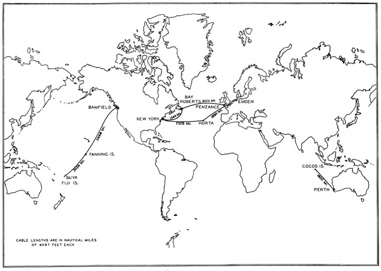
There are at present seven high-speed ocean cables of the permalloy-loaded type in operation. Together they have a length of nearly 15,000 miles, which represents about five per cent of the total ocean cable mileage of the world. Their location and lengths are shown on the map in Fig. 1. With the exception of the Cocos Island-Perth (Australia) cable of the Eastern Extension Telegraph Company, these loaded cables are comprised in three transoceanic lines, two crossing the Atlantic and one crossing the Pacific.
The first loaded ocean telegraph cable was the New York-Horta (Azores) cable of the Western Union Telegraph Company which was laid in September 1924. The great success attained with it led to the installation of others, among which was the 1926 Horta-Emden cable of the Deutsch Atlantische Telegraphengesellschaft. The New York-Horta-Emden line thus formed provides not only for carrying a large volume of messages between America and Germany, but also gives a connection with the Italian cable at Horta. This line is now provided with a 5-channel multiplex printing telegraph equipment which is operated at a speed of about 1500 letters per minute and is expected ultimately to be operated at a considerably higher speed. Four of the five channels of this line provide direct communication between New York and Emden, and the fifth serves for messages relayed at Horta.
A second transatlantic line is formed by the New York-Bay Roberts and Bay Roberts-Penzance cables of the Western Union Telegraph Company which were laid in 1926. Each of these cables is capable of carrying more than 2500 letters per minute, but at present this line is being operated at only about one half that speed. The construction of operating equipment to realize the full 2500 letters per minute is now in process. The combined traffic-carrying capacity of these two transatlantic loaded lines is nearly as great as that which was previously provided by the sixteen older non-loaded cables which served to connect North America with Europe prior to 1924.
The Pacific Cable Board, also in 1926, installed loaded cables to parallel its non-loaded cables of 1902, connecting Bamfield, Fanning Island and Suva. A speed of over 1200 letters per minute has been reported for each section of this transpacific line. This speed is nearly four times that which was afforded by the older non-loaded cables over the same route.
Such an extension of facilities for transoceanic communication would be expected to have a pronounced effect on both the cost of p. 227 p. 228 communication and the amount of communication between continents and, indeed, such an effect has already been experienced, significant reductions in rates having been made within the past year. In view of what has already been accomplished it seems not unlikely that the further introduction of loaded cables will completely revolutionize the whole transoceanic communication situation.
Historical
Like nearly all other important technical advances, that of the loaded telegraph cable is the outgrowth of contributions of many investigators and engineers working in different fields of endeavor. The history of the development of the idea of inductively loading transmission lines, from its original conception to recent times, is well known and need not be gone into here. An excellent theoretical analysis of the problem of transmitting signalling impulses over an ocean cable has been made by Malcolm, who in 1917, in his book on "The Theory of Submarine Telegraph and Telephone Cables," went so far as to predict that heavy continuous loading was the next great advance in the telegraph-cable art to be expected.
The practical accomplishment of the permalloy-loaded cable came about as a result of researches conducted in the laboratories of the American Telephone and Telegraph and Western Electric Companies, now known as the Bell Telephone Laboratories. Our interest in the problems of submarine cables was a natural part of our interest in all phases of electrical communication and was at first concerned principally with the application of vacuum tube amplifiers to ordinary telegraph cables. Considerable progress in the development of amplifiers for this purpose was made in the laboratory as early as 1914. The great demand for cable communication which the World War brought about led to further activity in this direction and to extensive tests of vacuum tube amplifiers on the cables of the Western Union Telegraph Company.
From these tests it was found that although the vacuum tubes would provide any desired amplification of signal strength and although by the combination of vacuum tubes and suitable electrical networks the distortion of the received signals could be corrected to any desired degree, relatively little actual gain in traffic capacity could be obtained by these means, since the real limit to cable speed was not distortion but interference. Although some improvement in cable speed could have been achieved by refinement of means for duplex operation and by improved means to eliminate extraneous interference, it was quite apparent that to obtain any great advance over the existing art would require a modification of the cable itself.
For over fifty years the cable had remained substantially unchanged in character, though great advances had been made in methods of operation. Inductive loading, which was proposed by Heaviside in 1887, was the obvious means for obtaining increased cable speeds, but no one had found a way to realize the advantages of loading as applied to ocean cables. Loading with evenly spaced coils as proposed by Pupin and used on land lines presented difficulties in laying and maintenance which practically prohibited this method. Continuous or Krarup loading by a wrapping of iron wire around the conductor of the cable was mechanically feasible but the amount of inductance which could be obtained in this way was not sufficient to justify its use. In order to make continuous loading advantageous for long ocean cables there was needed a material which could be much more easily magnetized than iron. Fortunately we had at hand as an aid to solving this problem the extraordinary magnetic material, permalloy, an alloy possessing magnetic permeability many times that of iron, even at the low magnetizing forces produced by the feeble currents of a telegraph cable. It is on permalloy that the loaded cable depends primarily for its success.
Although permalloy provided the means to give the cable the desired high inductance, the mere wrapping of this metal around the copper conductor of the cable was far from providing a practical solution of the problem of high-speed ocean telegraphy. To achieve this solution required the solution of very many subsidiary problems, concerned not only with the making of a cable but also with the transmission of signals over it and with the means for its practical operation. Work on all these phases of the problem of the loaded cable was actively pursued in our laboratories and in the field from the time of the first proposal, made in July 1919, to load a transoceanic cable with permalloy to the successful completion and operation of the New York-Horta cable.
During the first two years of this period our investigations were conducted wholly in the laboratory where hundreds of experimental lengths of loaded conductors were made and tested to convince ourselves that a permalloy-loaded cable could be manufactured and laid successfully. During the same period studies of the signal distortion of a loaded artificial cable and means for correcting distortion were carried on. Simultaneously methods of high-speed operation of loaded cables were developed, with the result that we were convinced from our laboratory experiments, not only that a permalloy-loaded cable could be made and laid successfully, but that it could also be operated commercially at the high speeds which we had predicted.
Having gone this far in the laboratory, it was decided to bring the results of our investigations to the attention of one of the cable operating companies with the object of securing a practical trial of a permalloy-loaded ocean cable.
On being shown what could be accomplished with permalloy loading, the Western Union Telegraph Company was quick to take advantage of this means of extending its cable facilities, and shortly thereafter arrangements were made whereby the Telegraph, Construction & Maintenance Company, Ltd., was to manufacture a cable for the Western Union Telegraph Company, using permalloy loading material supplied by the Western Electric Company and applied and treated under the direction of Western Electric engineers.
As a part of this undertaking, it was decided that prior to laying a complete transoceanic length of cable it would be desirable to make, lay and test a shorter length in order to obtain experience in manufacture and a test of its mechanical and electrical properties after it had suffered the extreme treatment to which a deep-sea cable is subject in laying. Accordingly, for such an experiment, 120 miles of cable of the same type which it was proposed to use for a transoceanic length was laid in a loop from the south shore of Bermuda in October 1923. Very thorough tests were made jointly by Western Electric and Western Union engineers to determine whether the electrical characteristics had been affected by laying and what attenuation and distortion were actually produced by such a cable. The results obtained were in excellent agreement with our predictions, and accordingly manufacture of the full 2300 miles required to connect New York and Horta was at once undertaken.
The New York-Horta cable which, like the 120-mile trial cable, was manufactured by the Telegraph, Construction & Maintenance Company with permalloy loading material applied and treated under the technical direction of Western Electric engineers, was laid in September 1924. Within an hour after the cable had been turned over to our engineers for test, a speed of 1500 letters per minute was obtained with the terminal apparatus which had been designed and provided in advance. In this case the messages were received on a high-speed siphon recorder of special design. Shortly thereafter, with the same apparatus, a speed of over 1900 letters per minute was obtained.
The speed of the cable having been demonstrated, commercial operation was quickly established with temporary operating equipment utilizing siphon recorders in conjunction with vacuum tube amplifiers. This type of operation was continued for about two p. 231 years during which the engineers of the Western Union Company and the Bell Laboratories worked together on the development of a multi-channel printing telegraph system which would adapt the operating methods previously developed by the laboratories to the needs of the telegraph company. In October 1926 the present five-channel printing telegraph apparatus was put into use.
Demands for other high-speed loaded cables quickly followed the successful demonstration of the New York-Horta cable. The Western Union Company arranged for the manufacture of the cables for the New York-Bay Roberts-Penzance route by the Telegraph, Construction & Maintenance Company, Ltd. On these cables permalloy supplied by the Western Electric Company was again used. The Norddeutsche Seekabelwerke A-G. arranged with the Western Electric Company for the supply of permalloy loading material and for technical assistance to manufacture the Horta-Emden cable for the Deutsch Atlantische Telegraphengesellschaft. The Pacific Cable Board arranged to have the cables for its Bamfield-Fanning Island-Suva line manufactured by two British companies and obtained licence therefor from the Western Electric Company. The shorter section from Fanning Island to Suva was made by Siemens Brothers & Co., Ltd., with permalloy supplied by the Western Electric Company and applied and treated with the technical direction of their engineers. The long section from Bamfield to Fanning Island was made by the Telegraph Construction & Maintenance Company, Ltd. All of these cables were laid in 1926.
Permalloy and Its Application to Cables
Permalloy, which made possible this radical change in the cable art, is the invention of G. W. Elmen of the Bell Telephone Laboratories. Since descriptions and explanations of some of its properties have already been given in papers by various members of the Bell Laboratories' staff,1 the present discussion will be limited to a brief statement of its outstanding characteristics which are of consequence in connection with its use on cables.
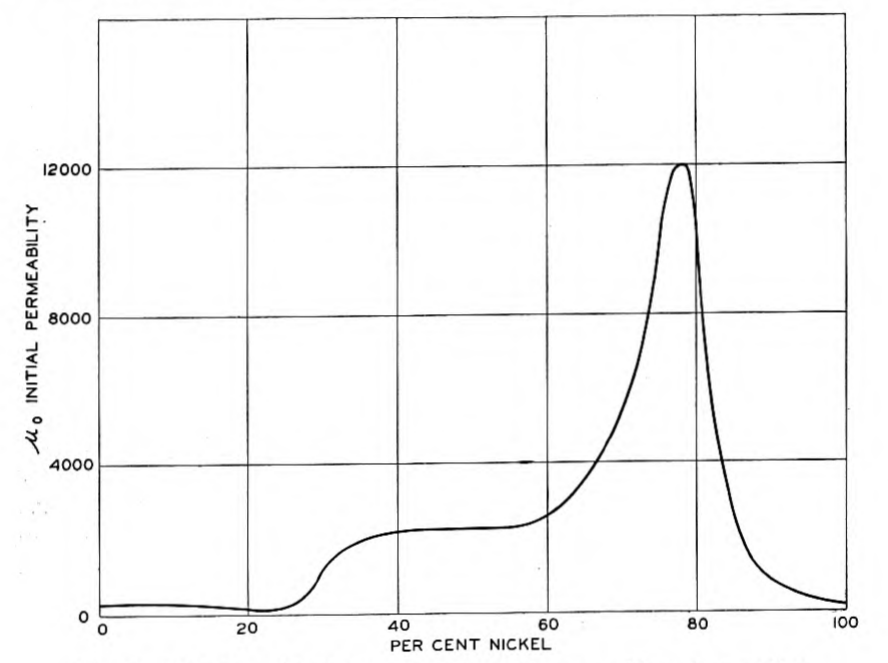
The name "permalloy" has been applied to alloys of iron and nickel of more than about 30 per cent nickel content characterized by extraordinarily high magnetic permeability at very low magnetizing p. 232 forces. The manner in which the initial permeability of these alloys varies with composition, when heat-treated in a particular way, is shown in Fig. 2, which is taken from the Arnold and Elmen paper. The magnetic properties of the alloys of this series depend in an extraordinary degree on their previous mechanical and thermal history. In general, high initial permeability is obtained by rapid cooling after a thorough softening of the metal by heating at a high temperature, this effect of rapid cooling being particularly marked on the compositions in the region of 80 per cent nickel. By control of the composition and heat treatment an initial permeability of more than 12,000 has been obtained with an alloy of 78½ per cent nickel and 21½ per cent iron, whereas iron or nickel alone ordinarily have initial permeabilities of only about 200 or 300. It is the high initial permeability of permalloy that is most important in its use on cables, though such an initial permeability as 12,000 would be even higher than is generally desired for a telegraph cable. For use on cable conductors permeabilities of the order of from 2000 to 5000 have been desired and obtained in practice.
Another important property of permalloy with regard to its use on cables is its resistivity, since high resistivity prevents excessive eddy-current p. 233 loss. The resistivity of the whole nickel-iron series of alloys is higher than that of either iron or nickel. By adding a third element, for example chromium, to the nickel and iron and keeping the ratio of nickel to iron about 4 : 1, a combination of very high resistivity and very high initial permeability may be obtained in the same alloy.
The permalloy used in the New York-Horta cable contained about 79 per cent nickel and 21 per cent iron with a small amount of manganese to make it more malleable. The permeability of this alloy as used on the New York-Horta cable was about 2300, its resistivity being about 16 microhm-cms. On the Horta-Emden cable, the New York-Bay Roberts-Penzance cables and the Fanning Island-Suva cable permalloy containing about 80 per cent nickel, 17.5 per cent iron, 2 per cent chromium and 0.5 per cent manganese was used. With this alloy an initial permeability of about 3700 was obtained. Its resistivity is about 38 microhm-cms.
The permalloy loading material used on the New York-Horta cable was in the form of a thin tape 0.006 inch (0.015 cm.) thick and 0.125 inch (0.32 cm.) wide applied in a closely wound helix surrounding the conductor. On the Horta-Emden cable tape 0.0059 X 0.098 inch (0.015 X 0.25 cm.) was used. On the New York-Bay Roberts and Bay Roberts-Penzance cables the tape thickness was 0.0055 inch (0.014 cm.) and the widths were 0.079 inch (0.20 cm.) and 0.123 inch (0.31 cm.) respectively. On the Fanning Island-Suva cable the permalloy is in the form of a wire of 0.011 inch (0.028 cm.) diameter applied in a single closely laid helix. The northern section of the Pacific cable from Bamfield to Fanning Island is reported2 to be loaded similarly with "Mumetal" wire of 0.010 inch diameter, made by the Telegraph, Construction & Maintenance Company.
Very good results have been obtained with both tape and wire loading. The tape has the advantages of costing less to apply and of possessing greater mechanical strength, whereas the wire has the advantages of lower eddy-current loss and of being less affected by the earth's magnetic field. With either wire or tape loading the component of the earth's magnetic field parallel to the cable sets up magnetic induction in the helical loading material and consequently reduces its effective permeability for the small magnetizing forces of the signalling current. This reduction of effective permeability by the earth's magnetic field is greater, the greater the angle of lay with which the loading material is applied. Consequently this effect is generally greater with tape loading than with wire loading. Whether p. 234 tape or wire should be used is, in the end, an economic problem since any disadvantage of one with regard to the other may be compensated for by increasing the size of the copper conductor.
Permalloy has another property which it is important to consider in connection with its use on cables, namely, its great sensitiveness to mechanical strain. Strain of deformation applied to it will modify its magnetic characteristics, and very great changes in its permeability for small magnetizing forces may be produced by strains well within the mechanical elastic limit. Consequently in making the cable it is necessary to insure that the permalloy shall be as free as possible from strains of deformation. There are two principal ways in which the permalloy used for loading may be subject to such strains. The first comes in the manufacture of the loaded conductor and the second in the laying of the cable.
Since permalloy is so strain-sensitive it must be annealed after it has been applied to the conductor. Accordingly the hard-worked metal is wrapped around the copper conductor and the conductor is thereafter passed continuously through a furnace, maintained at approximately 900° C, and from the furnace into a cooling tube. The lengths of the furnace and cooling tube and the rate of passage of the conductor are so chosen as to insure that the loading material will get the necessary softening in the furnace and will be cooled at the proper rate in the cooling tube. Even though the permalloy is thus annealed on the conductor, it still might well be subject to considerable strain, since the copper, on being heated to such a high temperature, expands more than the permalloy and tends to weld to it and, on contracting, would bend the permalloy tape near the spots where welding occurs. To prevent this action the loading material is applied very loosely and means are taken to prevent adhesion of the permalloy to the copper. In spite of the great sensitiveness of the permalloy to mechanical strain, the loaded conductor after heat treatment stands ordinary handling very well without much loss of permeability. However, if it were insulated by the methods which have been used in the past in making deep-sea cables, it would lose much of its inductance on laying on account of the effect of the great pressures to which a cable is subjected.
To prevent reduction of the permeability and consequent loss of inductance on laying, it is necessary to provide that pressure on the insulating material shall produce only true hydrostatic pressure on the permalloy with no tendency to deform it. This result has been accomplished by vacuum-impregnating the permalloy-loaded conductor with a semi-fluid compound which fills all the interstices of p. 235 the conductor and also forms a layer a few thousandths of an inch thick on the outside of the loading material. The gutta-percha insulation may then be extruded over the impregnated conductor with the assurance that the semi-fluid compound will serve to equalize the pressure on the permalloy. Numerous compounds have been proposed and used for this purpose, that on the New York-Horta cable being of an asphaltic type. It is essential, of course, that this compound be sufficiently viscous at temperatures at which the gutta-percha is applied to permit extruding the gutta-percha around it and that it will also be sufficiently fluid at the temperature of the sea bottom, which may be as low as 2° C., to permit readjustment of the pressure on the permalloy. When a loaded conductor insulated in this manner is subjected to high pressures at low temperatures, it may be found that the inductance drops when the pressure is first applied but in a few minutes the compound flows so as to equalize the pressure on the permalloy and the inductance quickly comes back to its original value.
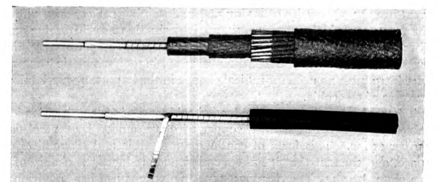
Outside of the insulated conductor or "core" of the cable the permalloy-loaded cables which have been made are quite like ordinary non-loaded cables, so there is no need to go into the further details of cable construction here. Fig. 3 shows a section of the deep-sea portion of the New York-Horta cable.
Principles of Design of Loaded Cables
There are two principal aspects of the design of a submarine cable— mechanical and electrical. Mechanically, the cable must be so designed as to insure that the conductor shall be continuous, that its p. 236 insulation shall be maintained and that the core, which comprises the conductor and insulation, shall not be damaged in laying or in subsequent repairing operations. Electrically, the cable must be so designed that it will serve properly to transmit signals. Thus the electrical design is concerned with the size of the conductor and the amount and characteristics of the loading material and insulation, whereas the mechanical design is concerned with the mechanical characteristics of the conductor and its insulation and with the jute and armor wire which serve to protect the core and give the cable the necessary strength. These two aspects of design cannot, of course, be considered quite independently of each other and both are in the ultimate analysis controlled by economic considerations. It is convenient for our present purposes, however, to consider them separately.
The mechanical design of cables is a well-established art and so great are the difficulties of laying and maintaining cables, even under the most favorable conditions, that it is desirable to avoid taking any liberties with this phase of cable construction. Fortunately the method of loading by a continuous wrapping of magnetic tape or wire introduces no need for radical change in the important mechanical features of the cable.
The copper conductor of the loaded cable is, as in many non-loaded cables, composed of a central copper wire surrounded by several flat copper strips. This form of conductor is flexible and economical of space, and the fact that it has several strands reduces the chance of a complete break. The loading tape or wire furnishes additional protection in this regard.
The thickness of gutta-percha must be sufficient to insure the integrity of the insulation at all points. It is, in fact, this consideration which established the amount of insulation used on the loaded cables which have been laid, since consideration of the theoretical economic optimum thickness of gutta-percha would in each case have demanded less gutta-percha than is considered safe. In this regard the insulating problem of the loaded cable is like that of the non-loaded cable.
The disposition of jute and armor wire around the core is determined wholly by mechanical considerations as in the case of the non-loaded cable for which the practice is fairly well standardized. Unlike the non-loaded cable, however, the loaded cable, in its electrical behavior, is affected somewhat by the presence and character of the armor wire as will be described later.
As is well known, the electrical behavior of non-loaded cables is determined almost wholly by their resistance and capacity and consequently the only important features to consider from the electrical p. 237 standpoint have been the size of the conductor and the thickness of insulating material. The electrical design of a loaded cable is, however, somewhat more complicated since in addition to copper resistance and electrostatic capacity we have here to be concerned with the inductance added by the loading material and also with added resistance factors which are introduced by its use. The problem of electrical design, therefore, involves determining not only the size of the copper conductor, but also the electrical and magnetic characteristics and the shape and dimensions of the loading material, as well as the electrical characteristics of the insulating material, which will give the highest speed of operation consistent with the mechanical and cost limitations which are imposed.
Since the object of the electrical design is to secure high operating speed, it is essential to consider what are the factors which limit speed and how they are taken into account. This subject has already been treated in some detail in previous papers,3 and only a general review of the principal factors involved in the electrical design will be undertaken in the present paper.
In the history of cable development prior to the introduction of the permalloy-loaded cable various physical factors at different times limited the speed of operation which could be obtained with a long ocean cable. These were principally distortion of signals, sensitivity of receiving apparatus, limited safe sending voltage, inaccuracy of duplex balance, and extraneous interference from both natural and man-made sources. With the development of cable amplifiers and of improved means of signal shaping, the factors of distortion and limited sensitivity of receiving apparatus were effectually eliminated and at the time when the development of the permalloy-loaded cable was undertaken the speed of long cables was limited in most cases by the accuracy with which artificial lines could be made to balance cables in duplex operation. In some cases where extraneous interference was unusually severe the limit of speed was set by that factor combined with the limit of sending voltage which was usually placed at about 50 volts by extreme concern for the safety of the cable insulation.
It was by no means obvious which of these several factors should be considered in the electrical design of a loaded cable. With the vacuum-tube amplifier available to amplify the weak received signal to the degree necessary to operate recording mechanisms, there was no practical limit to the sensitiveness of receiving apparatus. It was, however, necessary to consider distortion as a possible limit to speed.
It is interesting to note in this connection that, though, in most previous proposals to load long telegraph cables, loading had been advocated primarily as a means of reducing distortion, practical consideration of the problem uncovered new types of distortion which were absent in the non-loaded cable. The nature of distortion of signals by a non-loaded cable was well understood, the problem having been solved long ago by Lord Kelvin. The distortion of a loaded cable is a much more complex affair since there are involved in it not only the effects of distributed inductance, capacity, resistance and leakance of the ideal cable for which the distortion is readily calculable, but also the factors of change of inductance and resistance with frequency and current, and the effects of magnetic hysteresis which are unavoidable in a practical loaded cable. Though the effect of these factors on distortion could be approximated by theoretical analysis it was considered necessary to have experimental proof that a signal could be restored in shape after passing over a loaded cable and it was primarily on this account that tests were made with an artificial loaded line. These tests showed that even the distortion of a loaded cable could be corrected by using suitable terminal networks in connection with the vacuum tube amplifier.
With the factor of distortion thus eliminated there remained duplex balance, sending voltage and received interference as possible limits to the speed of the loaded cable.
Duplex balance would, of course, set the limit of speed of operation if the cable were to be operated simultaneously in two directions as is commonly done with non-loaded cables, since it would obviously be more difficult to build an artificial line electrically equivalent to a loaded cable with its variable inductance and resistance than one equivalent to a non-loaded cable in which only resistance and capacity have to be considered. Even with non-loaded cables the difficulty of balancing is so great that the double-duplex speed is usually much less than twice the possible simplex speed and with the loaded cable, which is more difficult to balance, the relative gain in traffic capacity to be obtained by duplexing is certain to be less than with non-loaded cables. On the other hand, simplex, or one-way, operation offers very great advantages especially when used in connection with automatic operation, since it disposes of the necessity for an intricate and costly artificial line and permits dividing the full traffic capacity of the cable most efficiently to accommodate the traffic it must carry, which with most transoceanic cables is usually unequal in the two directions. For these reasons it was decided to design the first loaded cable primarily to secure efficient simplex operation. Subsequent p. 239 experience has well justified this procedure for the cables which have been made.
The problem of designing a loaded cable was thus reduced to proportioning its component parts so as to secure the desired speed of operation under the conditions imposed by the limitations of sending voltage and received interference. Considerations of safety limit the sending voltage to about 50 volts, and terminal interference as ordinarily experienced requires that the received signal shall have an amplitude of a few millivolts. The risk of increasing the sending voltage to several hundred volts would not necessarily be serious but little advantage could be gained by taking this risk since, with the materials and type of construction used, higher sending voltage would involve increased hysteresis and eddy-current losses and consequently would not result in a proportionately higher received voltage. It is, however, possible to reduce the received interference by proper termination and this is of great importance in cases where the interference is severe.
The nature of cable interference and methods of reducing it have been discussed in a paper by J. J. Gilbert4 in which is described the method which has been used to decrease the terminal interference on the loaded cables which have been laid. This method consists in using, as the earth connection for the receiving apparatus, a "balanced" sea-earth, terminating in deep water. With ordinary cables the common practice has been to provide as the earth connection a sea-earth core, similar to the main core and sheathed with it, but extending only a few miles from shore to a point where the sea-earth conductor is connected to the sheath of the cable. While this type of earth greatly reduces the interference picked up in and near the cable terminal, it does not completely eliminate it. Almost complete elimination of the effects of disturbances originating between the termination of the sea-earth core and the shore may be obtained by providing a terminal impedance between the sea end of the sea-earth conductor and the sheath of the cable. For a non-loaded cable a combination of condensers and resistances would be required to make up such a terminal impedance, but for the loaded cable a very close approximation is secured by a simple resistance of a few hundred ohms. A few hundred feet of manganin wire, insulated like the rest of the conductor and joined to the end of the sea-earth core, serves this purpose admirably. This type of construction has been used on the New York end of the New York-Horta and on all terminals of the p. 240 New York-Bay Roberts-Penzance cables, on both ends of the Horta-Emden cable, and it has also been used in the loaded cables of the Pacific Cable Board.
With the maximum sending voltage determined and with the received voltage necessary to work through interference known, the cable can be designed to give the desired speed of operation. More specifically it is necessary to provide that the attenuation for frequencies essential to the formation of the signal shall be materially less than the attenuation corresponding to the ratio of the sending voltage to the interference at the receiving end. This condition can be met by establishing the attenuation of the cable for one particular frequency related to the speed of signalling. The relation between this frequency and the speed in letters per minute depends of course on the code and method of operation used. In the case of the New York-Horta cable the fundamental frequency of a series of alternate dots and dashes of the cable code, that is, one half the center hole frequency, was used as a basis for design. For this frequency a voltage attenuation of , corresponding to 87 TU, can be safely assumed for recorder operation under conditions of interference such as are encountered on the New York-Horta cable. With the Baudot type of code and using the most improved apparatus, that is including a synchronous vibrating relay, a voltage attenuation of , corresponding to 82 TU, may be assumed for the frequency resulting from assigning 1.25 cycles to a character of the Baudot code. .
The computation of the attenuation of a loaded cable requires, of course, only the substitution in the ordinary telegraph equation of the specific values of inductance, capacity, resistance, leakance and frequency which apply to the particular cable in question. The method of calculation of these electrical quantities has been discussed in previous papers and need not be repeated here.
The design of the cable is thus reduced to proportioning the elements of its construction so as to obtain the most economical cable of a given attenuation at a given frequency. The thickness of insulating material is, as has been noted above, determined practically by mechanical considerations. The electrical characteristics of the insulating material are effectively limited by the quality of gutta-percha, account being taken of its dielectric leakance which is of considerable effect on the behavior of the loaded cable though usually of almost negligible effect on non-loaded cables. With the possibilities of insulating materials thus limited the problem of electrical design reduces practically to determining the size of the conductor and the composition, size and shape of the loading material.
The desirable qualities in the loading material from the electrical point of view are high initial permeability, high resistivity and constancy of permeability in the range of magnetizing forces concerned. The exact composition of permalloy which would give the best combination of these properties would, of course, be different for different cables but for practical reasons it is desirable to choose a composition which approximates the optimum for general use. Having determined on a particular alloy, the optimum size of conductor and thickness of loading material may readily be computed on the basis of its known electrical and magnetic characteristics. With the compositions of permalloy which have been used, the optimum thickness of the layer of permalloy for a long ocean cable generally lies in the range from 0.005 inch to 0.010 inch which is fortunately convenient from the mechanical point of view. If less than the optimum thickness is assumed, the inductance will be too low and the consequent required conductor diameter will be too large. On the other hand, if more than the optimum thickness is assumed, the increase of eddy-current resistance and the effect of dielectric leakance will more than offset the gain due to the increased inductance.
In determining the optimum thickness of the permalloy it is, of course, essential to include all the resistance factors which are of consequence. In addition to eddy-current resistance and the effect of dielectric leakance there are the factors of hysteresis resistance and sea-return resistance which must, in particular, be taken into account.
The effect of hysteresis on attenuation is felt only near the sending end of the cable since over most of the length of the cable the current is so small that the hysteresis is negligible. Its effect near the terminals may be calculated by the method of successive approximations which takes account of the falling off of current and the change of hysteresis resistance with current amplitude. Ordinarily the effect of hysteresis becomes negligible beyond the first one or two hundred miles from the sending terminal. Within that range it may add as much as 10 TU to the total attenuation of the cable for the high-frequency components of the signals.
By sea-return resistance is meant the resistance which is contributed by the sea water and armor wire around the core of the cable. In low-speed non-loaded cables this factor may be safely neglected since the return current of low-frequency signals spreads out through such a great area around the cable that the resistance contributed by the sea water is negligible. With the high-frequency signals of the loaded cable, however, the return current tends to concentrate in the sea water close to the cable and much of it flows in the armor wires.
The result is a loss of energy which introduces resistance in the cable circuit, this resistance being much greater than if the armor wires were absent.5
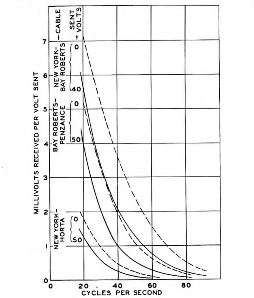
The relations between sent and received voltage for some of the cables which have been laid are shown by the curves in Fig. 4, in which the dotted curves give these ratios for zero sending voltage, obtained by extrapolation. These curves were obtained experimentally from the laid cables.
Principles Involved in Operation
To realize practically the full benefit of the high speeds of operation of which loaded cables are capable, required the development of new types of terminal apparatus. Although many of the functions performed by the apparatus on loaded cables are similar to those involved in the operation of ordinary cables, many new problems were introduced by the higher speed of the loaded cable and by its peculiar electrical characteristics. Also new means were required to secure efficient two-way working.
With both loaded and non-loaded cables the following steps are involved in operation: translation of messages into signal impulses and the application of these impulses to the cable; correction of distortion or, as it is commonly called, signal shaping; amplification of the feeble received impulses; and reconversion of the restored received impulses into messages. The requirements to be met in accomplishing the first and last of these steps with the loaded cable are different from those in the case of the non-loaded cable, principally on account of the higher speed of the former. The requirements to be met in signal shaping and amplification are different for the loaded cable both because of its peculiar distortion and because of its high speed of operation.
The means commonly employed on non-loaded cables for sending messages involves translation of a message, usually by machine methods, into electrical impulses of the standard cable code in which a dot of the continental Morse code is represented by a positive impulse of definite duration and a dash is represented by a negative impulse of the same duration. A train of impulses of equal length but of varying polarity is thus applied to the cable at the sending end. This train of impulses is distorted and greatly attenuated by the cable but is partially restored in shape and size by terminal apparatus and is finally received on a siphon recorder which makes a record in the form of a wavy line on a paper strip. In the form and spacing of the humps and depressions of this wavy line an expert operator recognizes the positive and negative impulses which were applied at the sending end and which he is able to translate into the original message.
The necessary correction of distortion of signals on ordinary cables is accomplished by simple electrical networks at the terminals. Advantage is also taken of the mechanical characteristics of moving coil instruments. The fundamental principles6 involved may be p. 244 roughly summed up as follows. For a line to transmit signals without distortion it would be necessary for all frequency components of the signals to be attenuated to the same degree and also for the delay or time-lag of transmission to be the same for all these frequencies. Legible signals can, however, be received if the attenuation of the combination of cable and apparatus increases with frequency, provided the increase in attenuation up to a certain value of frequency is not too great. Frequencies higher than this value are not required to form the received signal. For example, in the case of cable-code operation, a legible signal will be received if the attenuation at 1.5 times the fundamental or dot frequency is as much as 5 or 10 times the attenuation at the lowest frequencies involved in the signal, and if still higher frequency components are reduced to an inappreciable amplitude as a result of transmission through the system. The dots and dashes of the received signal will in this case be recorded as rounded but readily recognizable humps or depressions in the line traced on the siphon recorder strip.
Now the attenuation of the cable for the various frequency components is not uniform but increases rapidly with frequency. For example, on a particular transatlantic non-loaded cable a frequency of 2 cycles per second is received from the cable with one seventieth the amplitude which it had at the sending end, whereas for 4 cycles per second the received amplitude is one four hundredth of the sent amplitude and for 8 cycles per second it is only one five thousandth. The function of the distortion-correcting networks and apparatus is to attenuate the lower frequencies more than the higher ones so that the combination of cable and terminal apparatus will attenuate all frequencies up to a certain value approximately alike. The process of signal shaping may thus be regarded as one of attenuation equalization for a limited frequency band extending upward from zero. With the networks and apparatus employed on non-loaded cables the same means which serve approximately to equalize attenuation serve also to equalize time-lag. For frequencies higher than those required to form legible signals it is desirable to reduce the received current to as low a value as possible, since at such high frequencies the currents induced by sources of interference are usually stronger than those which belong to the signals. Accordingly the exclusion of these high frequencies makes the received signals more legible in being less affected by external disturbances.
The electrical networks for correcting distortion may be applied at either the sending or receiving end of the cable, or may be divided between the two ends. In ordinary cable practice it is common to p. 245 use a condenser in series with the cable at the sending end and to provide further means for signal shaping at the receiving end. The use of partial sending-end shaping has also been found desirable for the loaded cable though a modified circuit arrangement has been found more effective than the simple sending condenser.
Within recent years it has become common practice in the operation of cables to employ means for amplifying the received signals prior to relaying or recording them. This has been necessitated by the limited sensitivity of relays and recording instruments. Most of the amplifiers which have proved successful have been instruments of the moving-coil type in which a slight motion of the coil of a D'Arsonval galvanometer is caused to control a much larger source of power than that which is required to move the coil. Instruments of this type possess an advantage in that their mechanical inertia and stiffness may be used to assist in the processes of signal shaping and interference elimination. On account of mechanical limitations they are not, however, well adapted to operate at the high speed of the loaded cable.
Vacuum-tube amplifiers have been used to a limited extent on non-loaded cables and have many advantages over the moving-coil instruments, notably in their mechanical ruggedness and in the large amount of amplification which can readily be obtained with them. For use on loaded cables they have a further great advantage in that they have no frequency limitations within the range employed on cables and serve as well for high-speed cables as for low. By the use of suitable electrical networks in connection with the vacuum tubes the signals may be restored in shape, and interfering disturbances outside of the signal range of frequencies may be eliminated. A vacuum-tube amplifier which combines means for amplification, correction of distortion, and elimination of interference has been called a "signal-shaping amplifier."
With the combination of sending-end shaping network, loaded cable and signal-shaping amplifier, means are provided for conveying signals in the form of combinations of electrical impulses from one terminal to the other. Any type of telegraphic apparatus for converting messages into signals and reconverting signals into messages may be applied to complete the steps involved in one-way operation. None of the standard types of cable or land-line apparatus, however, are well adapted to meet the needs of commercial operation at the speed of the fastest loaded cables; to gain the full advantage permitted by the cable requires apparatus of special design. Special provision is also required to permit two-way operation.
There are two principal ways in which two-way working may be secured: messages may be sent simultaneously in the two directions or the cable may be used alternately in either direction. The first method is commonly called duplex and the second, simplex. Although, as was pointed out earlier in this discussion, the loaded cables which have been laid were designed primarily for simplex operation, it would be entirely possible to operate them duplex; but to do so would require the employment of an artificial line having nearly the same impedance as the cable over the range of frequencies involved in the signals. The speed of duplex operation would, of course, depend on the accuracy with which the artificial line could be made to balance the cable and this would be largely a matter of cost. Simplex operation, if the reversal of direction is made automatic, has much to recommend it over duplex. It does not require an expensive and complicated artificial line which would need frequent readjustment and it permits using the full speed of the cable to the best advantage to accommodate traffic. Means for reversing the direction may readily be associated with means for automatic printing operation and many of the objections to simplex working which are commonly thought of by the cable engineer do not apply when the reversal is thus made automatic.
Apparatus for the high-speed automatic operation of loaded cables has been described in recent papers by A. M. Curtis and A. A. Clokey. The Curtis paper7 deals principally with the apparatus for signal shaping and amplification, while the Clokey paper8 describes the special methods and apparatus for automatic printing telegraph operation. Some of the outstanding features of both classes of apparatus will be discussed in the following sections of the present paper.
Apparatus for Restoration of Signals
A typical circuit diagram of a loaded cable with its terminal networks for signal shaping and amplification is shown in Fig. 5. For the sake of simplicity the circuit details required for two-way operation have been omitted. Such a circuit arrangement applied to a transoceanic permalloy-loaded cable serves to connect a telegraph transmitting instrument with a receiving or recording instrument for one-way operation nearly as effectively as they could be connected by an overland telegraph line.
At the sending end in place of the usual sending condenser there is employed the network shown in the figure. The condenser may have a capacity of from 30 to 80 microfarads. It is shunted by a resistance of several thousand ohms. The resistance connecting the sending end of the cable to earth may be of the order of 100 ohms, and serves approximately to equalize the input impedance of the system over the important range of frequencies. The desirability of the resistance is peculiar to the loaded cable and is occasioned by the manner in which its characteristic impedance varies with frequency.
Other sending-end circuit arrangements can, of course, be used and networks combining inductances with capacities and resistances have been effectively employed. The sending-end shaping network may even be dispensed with entirely and all of the shaping done at the receiving end. There are, however, certain conditions under which this leads to the production of distortion due to hysteresis in the magnetic material of the cable and in general it is preferable to reduce the current flowing into the cable by employing sending-end shaping networks which reduce the amplitude of the low-frequency components of the signal.
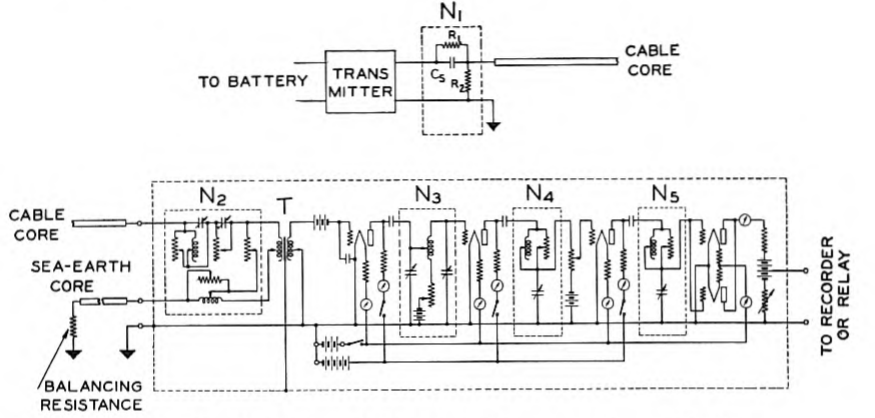
The circuits employed at the receiving end for completing the process of signal shaping and for amplifying the signals may conveniently be considered in three parts, the receiving shaping network , the shielded transformer , and the amplifier which includes the interstage shaping networks , and .
The receiving network provides means for correction of a considerable part of the distortion introduced by the cable and in so p. 248 doing reduces the peak voltage which is applied by the signals to the primary of the transformer and also the peak voltage which is applied to the grid of the first vacuum tube. By insertion of this shaping network between the cable and the transformer, overloading and consequent distortion are prevented.
The transformer permits insulating the amplifier and its batteries from the cable and thereby allows the amplifier to be connected directly to earth9 and to be effectively shielded from local electrical disturbances. Without the transformer or other means to insulate the amplifier from the cable it would be impossible to use an earthed amplifier and at the same time to secure the advantage of the balanced sea-earth in eliminating interference. The requirements for this transformer are very severe since it must be effective for frequencies as low as 0.2 cycle per second and at the same time must be constructed so that it will not pick up the external electrical disturbances generally prevalent in cable stations. The use of a permalloy core and a permalloy shield has made it possible to meet these requirements in an instrument occupying less than one third of a cubic foot.
Connected between the successive stages of the amplifier are the signal-shaping networks , and . These networks serve both to adjust the shape of the signal and to reduce the effects of interference outside of the signal range. Considerable advantage is gained from the fact that there are in the entire system five signal-shaping networks, each separated from its neighbors by either the cable or the vacuum tubes. This arrangement permits independent adjustment of the separate networks with very little interaction between them and greatly facilitates the systematic correction of signal shape.
The values of the various resistances, inductances and capacities in the networks at the receiving end depend, of course, on the cable as well as on the type of telegraph apparatus employed; for this reason most of the important circuit elements are made adjustable. The adjustments are made by trial, but in spite of the apparent complexity of the networks, which are more elaborate than would be required for any given cable with fixed operating requirements, the adjustments necessary to adapt the apparatus to any particular conditions can be made quite systematically. After the shaping adjustments required for a particular cable have been worked out, which usually takes not more than a few days, the amplifier can be adjusted for any speed in the range of the cable in a few minutes.
The output of the amplifier may be applied to a siphon recorder or to relays, as desired, and the amount of amplification may be adjusted over a wide range to meet the requirements of any particular case. In general the power amplification needed for automatic operation of a loaded cable at its maximum speed is of the order of 10,000,000 times, which corresponds to 70 TU.
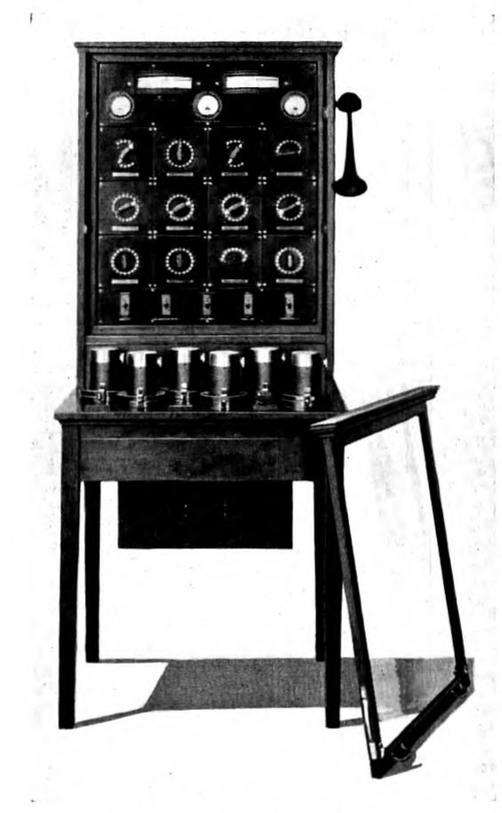
The external appearance of the signal-shaping amplifier is shown in Fig. 6. All of the receiving circuit elements shown in Fig. 5 are contained in its shielded case which is made of ample size so that all of the essential apparatus units within it are readily accessible. Great care has been used in the design and construction of the amplifier unit to protect the circuit elements within it from moisture and to prevent leakage or electrostatic coupling. The output terminals of the amplifier may be connected directly to a siphon recorder or to a suitable relay. However, when the amplifier is used for the operation of relays and multiplex printing telegraph apparatus, there is associated with it an additional piece of apparatus called the relay control desk p. 250 which is shown in Fig. 7. In this unit is provided means for control and adjustment of the relays and also means to compensate the type of signal distortion commonly described as the "wandering zero" which results from the inability of the system as shown in Fig. 5 to transmit direct current.
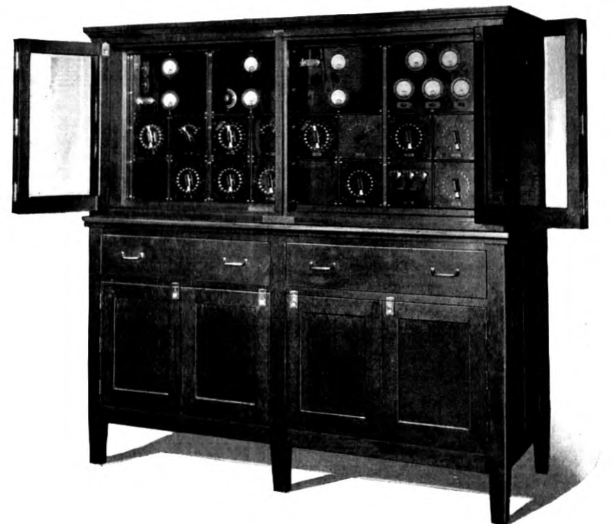
Amplifiers of the type described are in commercial operation at all terminals of the Western Union and Deutsch Atlantische loaded cables. In this extensive commercial use they have been shown to require considerably less maintenance than the moving-coil instruments which are commonly used on non-loaded cables, and in fact the loss of time in operation due to troubles in the amplifiers has been almost entirely negligible. It is of interest to note that it has been possible p. 251 on numerous occasions to operate cables with these amplifiers during the entire course of severe thunder storms with the loss of only an occasional letter due to lightning discharges.
Apparatus for Automatic Operation
The first operating tests of the New York-Azores cable were made with the signal-shaping amplifier described in the preceding section. For these tests cable-code operation with a siphon recorder was employed, this type of operation being chosen because it would permit direct comparison of the behavior of the loaded cable with that of ordinary cables. The ordinary cable-code transmitters and siphon recorders were, however, incapable of operation at the predicted speed of over 1500 letters per minute and a new transmitter and recorder had to be provided for testing and demonstrating the operation of the new cable.
The high-speed transmitter which was developed for these tests is shown in Fig. 8. This transmitter makes use of the ordinary perforated tape used with standard types of cable transmitters but instead of opening and closing contacts by mechanical means it employs pneumatic means for this purpose, the perforated transmitting tape being utilized in the manner of the perforated sheet in a player-piano.
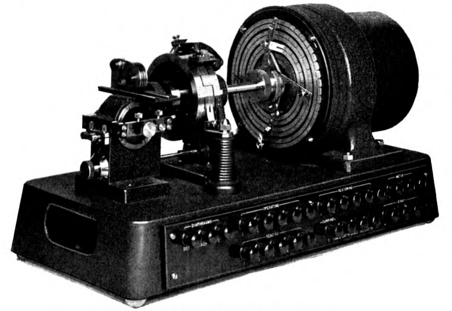
A commutator and relays associated with the pneumatic apparatus serve to equalize the lengths of the transmitted signals and to provide any desired ratio of "marking" to "spacing." This transmitter is capable of operating at speeds up to about 2500 letters per minute.
The high-speed siphon recorder is shown in Fig. 9. It differs from the standard instrument in many respects. A very light moving coil is supported horizontally in the strong field of an electromagnet by a bifilar suspension. A very light rigid arm attached to the coil carries a siphon pen only about 2 cm. long which writes on ordinary recorder tape drawn rapidly over a vertical table. This instrument may also be operated at 2500 letters per minute with cable-code and makes a record similar to that of the standard siphon recorder.
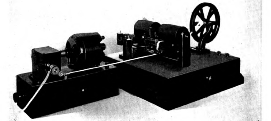
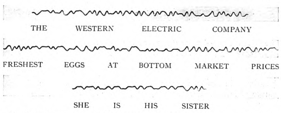
Both of these instruments and the signal-shaping amplifier were provided in advance of laying the first permalloy-loaded cable and were used on the first tests. A record of an early test message made on the New York-Horta cable at a speed of 1920 letters per minute is shown in Fig. 10.
Since this first cable terminated at the Azores Islands where there was no immediate demand for the full speed of which the cable was capable, the first commercial operation was conducted at a speed of only about 800 letters per minute. This was obtained with a standard cable-code transmitter and a standard type of recorder used with the signal-shaping amplifier. The cable was operated alternately in the two directions as required to accommodate traffic, the reversal of p. 253 direction of operation being controlled manually. While this type of operation served well to carry the limited traffic then available, it was not suited for efficient operation of the cable at its maximum speed, both because of the practical difficulty of dividing the rapidly received recorder tape among the three or more operators who would be required to translate it, and because of the delays resulting from manual control of reversal of direction.
To make efficient use of a high-speed telegraph cable requires some means of adapting it to the practical limitations of machines and operators, preferably by the provision of a number of separate channels of operation, each of which may be worked at a speed consistent with the pace of a single operator at each end of the cable. With such multi-channel operation it is obviously necessary to provide means for either simultaneous two-way working or automatic means for direction reversal which shall not interfere with the independent operation of the several channels. Also it is very desirable to provide for automatically printing the received messages.
There are two principal methods which have been used to secure multi-channel operation with a single telegraph line—the carrier current method and the multiplex distributor method. By the former the separate channels are obtained by the modulation of separate carrier frequencies in accordance with the telegraphic signals, the line being simultaneously shared by all the channels; by the latter the line is passed in rotation from one channel to the next so that the line time is in effect divided equally among the several channels. Either method or a combination of the two can be applied to a loaded cable. The carrier current method has for several years been used on the loaded cables of the Cuban-American Telephone Co. between p. 254 Key West and Havana and has also been used on some non-loaded cables and quite extensively on land lines. The multiplex distributor method is used widely on land lines and has also been used to some extent on non-loaded cables. Of the two the multiplex distributor method makes more effective use of the line when the frequency-range is limited to about 100 cycles per second or less and the carrier current method is more effective when a considerably wider frequency-range is available. Since the frequency-range provided by the New York-Horta cable extended to about 60 cycles per second, the multiplex distributor method was the more effective means for providing multiple channels on this cable and was accordingly adopted.
With the multiplex distributor method of separating channels several different systems of operation employing different signal codes are possible and several different codes have been practically applied. Among these are the cable-code, the three-unit three-element code and the five-unit two-element or Baudot-type code. To determine which of the several possible systems can give the greater speed of operation is an extremely complex problem since it requires consideration not only of the number of characters or letters and their frequency of occurrence in messages but also of the line characteristics and the nature of interference. From the practical point of view, however, the multiplex system, which employes a code of the Baudot type, has the great advantage of availability of perfected transmitting and printing apparatus and, in view of this advantage, there seems little doubt of this being the best system for the immediate practical realization of the possibilities of a loaded transoceanic cable. In this system the line-time is divided into as many parts as there are channels of communication and each of these parts is divided into five units. The line is thus used in effect to transmit five successive signal units of either positive or negative polarity from one transmitter to its corresponding receiver, thereby sending one letter or character over one channel. It is next used to send similarly another letter on another channel and so on until a letter has been sent over each channel, whereupon a second letter is started over the first channel.
Although multiplex distributors for land lines had long been available, the standard apparatus was not suitable for realization of the full advantage of the permalloy-loaded cable. This was appreciated from the first, and long before the manufacture of a loaded cable was started the development of a system for operating it was undertaken. In several important respects the apparatus developed for the cable is different from that used on land lines.
Two-way operation is provided by automatic reversal of the direction p. 255 of sending. This is accomplished by driving from the multiplex distributor a reversing mechanism which switches the cable from sending eastward to sending westward or vice-versa at regular intervals without the loss or mutilation of a character on any channel. To adapt the apparatus to the demands for traffic, the intervals of reversal are made capable of variation over a considerable range so that the system can be used, for example, alternately one minute eastward and ten minutes westward or three minutes eastward and three minutes westward, only about five seconds being lost at each reversal.
To secure the maximum speed of operation, use is made of the "synchronous vibrating relay," a method of signal restoration developed in the course of our laboratory studies of apparatus for loaded cables. The synchronous vibrating relay takes advantage of the principle of the Gulstad vibrating relay, which has been extensively used on both land-lines and cables, but possesses a further advantage in that use is made of the synchronous multiplex distributor to secure the most effective application of this principle.
To describe and explain the circuits and apparatus of the synchronous p. 256 vibrating relay would be beyond the scope of this paper but the way in which it permits an advantage in speed of operation may readily be appreciated from a consideration of the signals shown in Fig. 11.
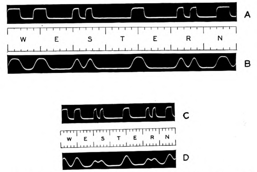
Consider first the conditions in plain relay operation without the use of the vibrating relay principle. The signal train A, Fig. 11, represents the word "western" as translated into the code used in the multiplex printing telegraph system. If this word is transmitted over the combined cable and distortion-correcting networks at a suitable speed for plain relay operation, it will be received in the form, B, in which a transmitted impulse of unit length has resulted in a received impulse of about the same amplitude as that of impulses two or more units long. A simple relay operated by the signal train, B, will substantially reproduce the original transmitted train, A.
Consider now the signal train, C, in which the same word "western" is transmitted at twice the speed of A. With the same adjustment of cable and terminal networks it will be received in the form, D, in which impulses of two units of length are received with the same amplitude as that with which the unit length impulse was received in B, whereas the amplitude of a succession of received reversals of unit length in D is reduced nearly to zero. Obviously, if D were applied to a simple relay, it would not cause the original signal train, C, to be reproduced. However, C can be reproduced from D by means of the synchronous vibrating relay which is arranged to supply impulses of unit length locally, unless prohibited from so doing by currents due to impulses of two or more units of length. One may regard the cable and terminal networks as converting the transmitted two-element (plus and minus) signals into three-element (plus, zero and minus) signals which the vibrating relay reconverts into two-element signals, and in this way permits operation at a speed which is much higher than is possible with a plain relay. With the Gulstad relay or with minor modifications of it, the locally interpolated impulses are supplied from a local vibrating circuit and do not always occur at exactly the right time to be most effective. With the synchronous vibrating relay, these impulses are controlled by the distributor and are therefore introduced at precisely the right time. It is interesting to note that this can be done in a system in which the incoming signals control the rate of the distributor.
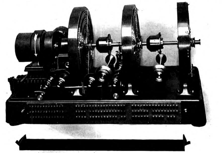
Another feature of the apparatus for the loaded cable is its high degree of precision and refinement. The cost of a cable relative to that of even the most refined apparatus is so great that no considerable sacrifice of speed can be justified by ordinary economies in apparatus. p. 257 Accordingly, the efficiency to be gained by extreme precision has been sought, and to achieve this desired precision has required radical departure from the design used in land line apparatus. A photograph of one of the distributors used on the New York-Horta-Emden line is shown in Fig. 12. On this line three 5-channel distributors are used, one each at New York, Horta and Emden. Within a few seconds after one of five operators at New York prepares a perforated strip on a machine resembling a typewriter, the message appears in typewritten form in Emden on a strip ready for delivery or retransmission over a land line.
While the system which I have roughly described is one which was developed principally with regard to use on a particular cable, the principal features embodied in it are applicable to any long loaded cable of the type discussed in this paper. The details of the apparatus which should be used on any cable are of course dependent on the particular requirements to be met and each installation must be engineered for its special needs if the full benefit of loading is to be realized.
Electrical Measurements of Loaded Cables
To check the assumptions made in the design of the first cables, and to obtain the information necessary for the design of the ultimate operating equipment, extensive electrical measurements were made on the three Western Union cables after they had been laid. From an analysis of these measurements the several electrical parameters of the cables were determined. To do this required new apparatus and methods, the development of which was by no means a small part of the total effort involved in the first project. Since a review of some of the methods of measurement has been given in a recent paper by J. J. Gilbert,10 the present discussion will be limited to the apparatus and methods which seem to be of particular interest.
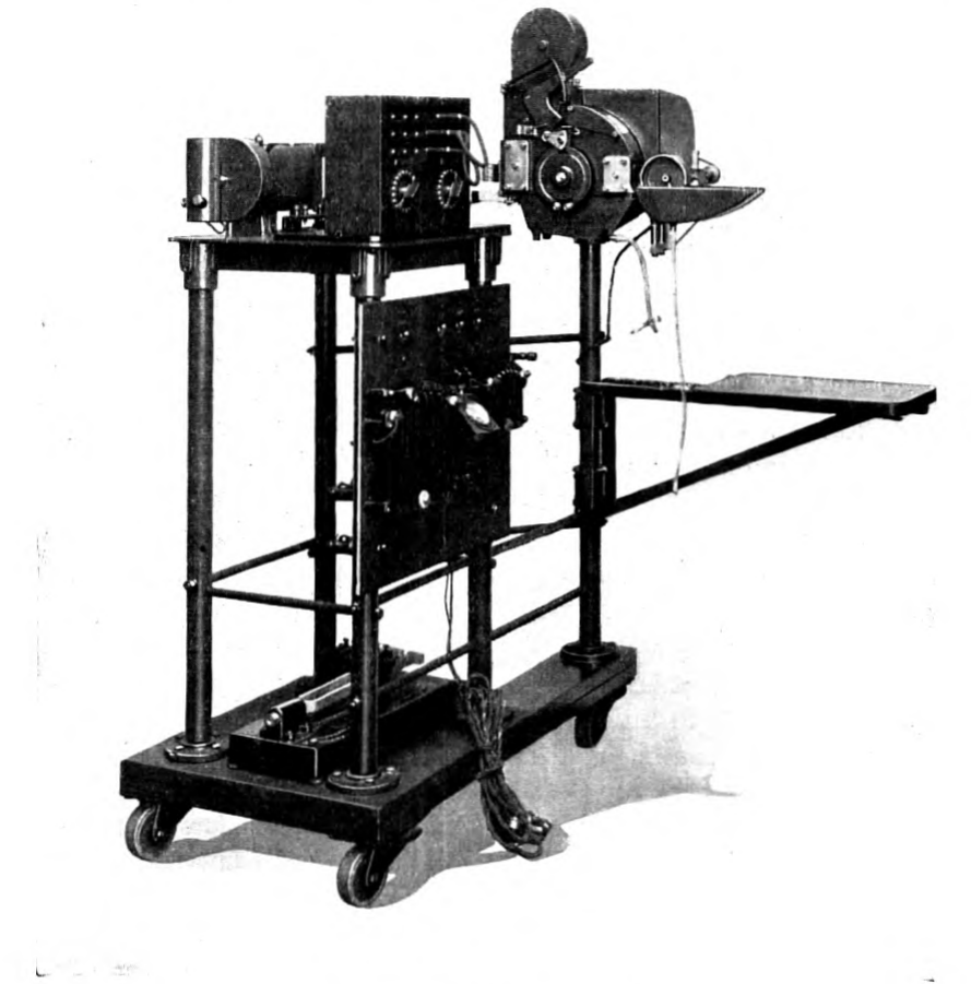
One of the most important tools in all our investigations concerned with the permalloy-loaded cable was the string oscillograph shown in Fig. 13. From the start it was recognized that an instrument would be needed which would give an accurate record of the manner in which the currents and voltages which were being studied changed with time and, in fact, the first step in the experimental investigation of the cable problem was to search for a suitable oscillograph. Fortunately it was not necessary to look far. A string oscillograph which had been developed for sound-ranging of artillery during the World War was quickly modified and devoted to more peaceful purposes. The present instrument differs in many details from the original but retains the invaluable asset of ability to give almost instantaneously, completely developed and fixed, a distortionless picture of a wave involving any frequencies up to about 300 cycles per second. In a study like that of signal shaping, involving the determination of the effect of numerous slight changes in adjustment of the apparatus, the advantage of such an instrument is obvious. This instrument was used both in the early studies of signal correction with the laboratory artificial cable and in the later measurements on the laid cables, and today is a useful adjunct in cable stations where it serves to show the character of the cable signals at any stage of their conversion into impulses for the recording instruments. A feature of particular value in studying phenomena such as extraneous interference on cables is that the oscillograph permits taking a continuous record over a period of several minutes.
Other special instruments which I shall only mention, but which were developed especially for the cable experiments, were an attenuation meter and a low-frequency vacuum-tube oscillator to give p. 259 voltages of constant frequency as low as 2.5 cycles per second and of very pure wave form.
To determine the various electrical parameters of the laid cable wholly from measurements at its terminals was practically impossible on account of the complicated manner in which the resistance and also to some degree the inductance and leakance vary with frequency. However, by combining the results of factory measurements with the results of measurements made at the cable terminals it was possible to determine the fundamental characteristics of the laid cable with a fair degree of accuracy. The method consists essentially in measuring, at a number of frequencies ranging from 5 cycles per p. 260 second to the highest frequency possible, the attenuation and delay or time-lag of trains of reversals transmitted over the cable.
Attenuation was measured by transmitting square-topped reversals of constant voltage and frequency and measuring the received current by means of either an amplifier and thermocouple or an amplifier and the string oscillograph, the latter method being preferable at high frequencies where the effect of interference would prohibit accurate measurement by means of the thermocouple.
The delay for steady alternating currents was measured by transmitting short trains of reversals alternately from the two ends of the cable, the transmitted and received trains at each terminal being recorded by means of the string oscillograph on a continuous strip of paper. Thus in a single cycle of operations the record at one terminal would show a transmitted train followed by a received train, while the record at the other terminal would consist of a received train followed by a transmitted train. Since a certain time is required for the establishment of the "steady state" condition at the receiving end, it was found desirable to base the measurement of the time of arrival and departure on a point well along in the train, say at the fifth to tenth cycle. The difference in elapsed time between sending and receiving at the two ends of the cable then gave twice the steady-state delay or "time of propagation" for the particular frequency for which measurements were made.
Both attenuation and delay were measured for several current values and by extrapolation to zero current the values of these quantities corresponding to a very small current amplitude could be determined. Measurements made on cores in the factory under various conditions of temperature and hydrostatic pressure gave a value of capacity for the cable and from this and the measured delay the inductance could be computed. Knowing the inductance and the capacity, the effective resistance of the cable at various frequencies could be computed from the measured values of attenuation, the value of leakance being estimated from factory measurements. This value of effective resistance should agree with the value obtained by adding together the various known components of resistance. Of the components of resistance, the copper resistance and the resistance introduced by the loading material can be computed from measurements made in the factory. The sea-return resistance can be computed from theoretical formulas and the effect of reflections from irregularities along the cable can likewise be estimated.
For the cables on which such measurements have been made, the values of effective resistance obtained from cable measurements agree p. 261 to within less than 5 per cent with the values computed as described. Part of this difference is probably due to the fact that the computed values of sea-return resistance are smaller than those actually encountered on the cable. A possible explanation of this effect is that the electrical resistivity of the earth beneath the cable is considerably higher than was assumed in the theoretical development of the formula for sea-return resistance.
A General Survey
The preceding discussion has referred principally to the progress in certain lines of development which were chosen as best suited to accomplish the result of high-speed ocean cable telegraphy. It is of interest now to consider in a general way the field of application of loaded telegraph cables and the nature of modifications which might be made in their construction and operation.
All of the loaded telegraph cables to which I have referred are relatively long. That permalloy loading should have been applied first to long cables is the natural consequence of the facts that the need for increased cable speed was principally between points far apart and that the greatest economic gain from loading could be obtained with long cables. Where high-speed cable operation was desired between points only a few hundred miles apart, it could readily be obtained with a non-loaded cable by merely making the cable large enough to give the required speed. Accordingly for short cables the operating speed was determined either by the demand for communication or by limitations of terminal apparatus. But where the necessary length was of the order of 2000 miles or more, even the heaviest cables which were considered practicable to lay and maintain were limited by the inherent characteristics of non-loaded cables to relatively low speeds, and it was accordingly for such great distances that the manifold speed advantage of the permalloy-loaded cable was of the greatest value.
To give a fair numerical estimate of the advantage of loading long cables is extremely difficult since the result depends so much on the basis of comparison and the limitations of size and operating requirements which are imposed. Probably the most nearly fair basis of comparison would be the relation of cost to speed for the old and for the new cables, but to make such a comparison requires data on cost which is forever changing. An interesting basis of comparison from the technical point of view is the ratio of the traffic capacity of a non-loaded cable operated duplex to that of a loaded cable operated p. 262 simplex, both cables being of the same length and size. The latter condition will be met if the diameter of the loaded conductor measured over the permalloy is the same as that of the copper conductor of the non-loaded cable and if the thickness of gutta-percha is the same for both. On this basis one can say that for cables of lengths from about 2000 to 3500 miles the loaded cable has approximately five times the traffic capacity of the corresponding non-loaded cable, this gain being obtained, of course, with a relatively small increase of cost.
A similar comparison might be made for shorter cables but it would have relatively little significance since in any practical case the loaded cable would probably not be made to have the greatest possible speed consistent with practicable size but would be designed with regard to the limitations of terminal apparatus or connecting lines. The problem becomes more complex as the assumed length is reduced since the shorter is the cable the greater are the number of possible ways of obtaining the desired speed and the more is the speed dependent on terminal equipment. It is, however, safe to say that, where the demand for communication is sufficiently great, loading will prove advantageous for cables of all lengths down to perhaps 100 miles or less, but for cables much less than 2000 miles long the electrical design of any particular cable will depend greatly on the use which is to be made of it.
In view of the great gain due to loading long cables it is most probable that all very long cables of the future will be loaded and it is likewise probable that long cables will be used in some cases where previously several short non-loaded sections with repeating apparatus would have been used. Loading will also be used to a considerable extent on shorter cables but it should not be expected that all of the shorter cables will be loaded since there are many cases where the demands for communication which can now be foreseen are so limited that they can be met more economically by non-loaded than by loaded cables.
In Malcolm's prediction of the loaded ocean cable, to which I have previously referred, he went so far as to suggest that even though the first loaded ocean cable would probably be of the continuously loaded type, ultimately coil-loading might be resorted to. Malcolm, of course, was not in a position to take into account the effect of such a radically new material as permalloy, and with the materials which were known to him coil-loading appeared to offer possibilities which continuous loading did not. It is interesting therefore to examine the present apparent merits of coil-loading with regard to its application to transoceanic cables.
An obvious great difficulty with coil-loaded deep-sea cables lies in the mechanical problem of laying a cable to which coils are attached or in which coils are inserted in a way to give a mechanical irregularity. Unless the coils could be made extremely small their presence would certainly interfere with passing the cable smoothly through the paying-out machinery. Cable laying and repairing are sufficiently difficult and hazardous under the most favorable conditions and any alteration in cable structure which would make these tasks more difficult is certainly to be avoided if possible. Permalloy cores for loading coils might, however, to some degree eliminate this objection to coil-loading, since with a permalloy core the loading coils may be made smaller with the result that less difficulty would be caused by the increased size of the cable at the points where the coils were inserted.
The problems of maintaining good insulation and sound joints at the loading coils are probably much more serious. Conductor joints in a cable are frequently subject to considerable stress and even with the relatively simple joints required for ordinary deep-sea cables trouble is occasionally experienced. With loading coils inserted in the cable both the coils and the joints between the coils and the core must be subject to great stress, and since the coils must be many in number to be effective, the probability of faults with even the best imaginable construction would be greatly increased.
From the electrical point of view an apparent advantage of coil-loading is that it might conceivably permit adding the required inductance without introducing so much a.c. resistance and thereby permit more closely approximating the ideal loaded cable. On the other hand, coil-loading has an electrical disadvantage which has not generally been appreciated but which is of serious practical consequence. This disadvantage lies in the distortion of signal-shape arising from the lumped character of the line. With uniform continuous loading the line is electrically smooth; such a line may introduce distortion but this distortion can be compensated for by terminal apparatus. With coil-loading the line is, in effect, a network of as many sections as there are loading coils. Such a line introduces a new type of distortion which arises in the so-called filter oscillations. Although it is theoretically possible to compensate for this effect by terminal networks, the circuits required are extremely complex and practically the limit of speed is set by the frequency of signal impulses at which filter oscillations begin to cause serious distortion. This effect can be practically eliminated by making the distances between coils sufficiently small, but as the distance between coils is diminished the otherwise possible advantages of coil-loading are likewise diminished.
Even if it could be shown that all of the apparent objections to coil-loading could be overcome, I think it is highly improbable that coil-loading would be resorted to for long deep-sea telegraph cables. Continuous loading has been given a practical trial and has proved successful and does not add greatly to the cost of a cable. Coil-loading involves risks which there is now no need to assume and its economic advantage, if any, is certainly small in proportion to the whole cost of a cable installation.
Though continuous loading as applied in several particular instances has been successful, there is no occasion to assume that the development of the art of continuous loading is completed. Modifications in continuous loading can be introduced with relatively little risk and are justified if an economic advantage can be shown. Also cable construction, apart from the loading, may be modified so as to realize more completely the advantages which loading affords. It is therefore of interest to consider some of the ways in which continuously loaded cables of the future might be different from those of the present.
Loading materials can be produced with different magnetic properties and to a limited extent the resistivity of alloys may be altered by control of composition. Higher permeability is not necessarily desirable since with increased permeability goes also increased effective resistance due to energy losses in the permalloy. In the case of any particular cable with practical limitations of dimensions, materials and costs there is an optimum permeability which, in general, is lower the higher is the frequency for which the cable is designed. Short cables designed for very high frequencies will accordingly require lower permeability than has been required for the long cables which have been made. For cables of all lengths and speeds a high degree of constancy of magnetic permeability with regard to magnetizing force is desirable. With the New York-Horta cable the inductance increases about 50 per cent when the current is increased from 0.001 to 0.1 ampere. The relative increase is less for some of the later cables, owing to improvements in loading. A loading material of high electrical resistivity is, of course, always advantageous.
There are other ways of applying continuous loading than that of Krarup. For example, the magnetic material may be electroplated onto the conductor. Such modifications may eventually come into use but the need for them does not appear to be great in the case of long deep-sea cables and there is not much economic incentive for their development. Accordingly I do not believe that changes of this type are likely to alter greatly the possibilities of submarine cables for telegraphy over long distances.
The cost and physical characteristics of insulating materials are, of course, factors of great importance. With few exceptions gutta-percha or compounds consisting mostly of gutta-percha have been used for long submarine cables. The cost of the gutta-percha insulation is a large part of the whole cost of a cable and the fact that its cost is high leads to using the least amount consistent with maintaining safe insulation. If a very much cheaper substitute or one of superior electrical properties were available, the basis of design of loaded deepsea cables might be somewhat changed.
Even the sheath of armor wires is capable of considerable improvement as regards its effect on the behavior of a loaded cable. As pointed out previously, the sheath introduces electrical resistance due to the fact that it carries some of the return current which at high frequencies tends to concentrate around the cable. Armor wire of higher resistivity would introduce less resistance in this way or an electrical improvement might be obtained by consideration of this effect in the mechanical design of the cable sheath. At very high frequencies where the return current is closely concentrated around the cable the armor wire has an opposite effect and an improvement can be obtained by decreasing its resistance or by the addition of other conductors in parallel with it as was done on the Key West- Havana telephone cables. Some electrical resistance is introduced by the magnetic coupling between the sheath and the conductor due to the helical shape of the loading material and the armor wires. This effect is small in the cables which have been made but might be large in higher speed cables and should be taken into account in the design of such cables. A similar effect results from the use of the ordinary teredo tape on loaded cables.
With improvements in materials and construction which permit higher operating speeds and with the demand for more efficient means of handling a large volume of cable traffic, greater importance will doubtless be attached to duplex or simultaneous two-way operation, and it is of interest to consider some of the ways in which duplex operation might be secured. Of course there is no reason to assume that the loaded cables which have already been laid will not eventually be operated duplex although they were designed primarily with simplex operation in view. From the studies of both types of operation which we have made it appears more economical for the present to operate the existing transatlantic loaded cables one way at a time. Indeed this type of operation with automatic reversing apparatus possesses many advantages over the ordinary duplex methods applied to non-loaded cables. If, however, a loaded cable were designed p. 266 originally with regard to duplex operation, the possible advantage of applying duplex apparatus to it would obviously be greater than it is for any of the existing loaded cables.
There are many ways in which the design of a cable might be modified to make duplex operation more advantageous than it is on the present cables, and the problem is much too complex to permit very detailed discussion here. Improvements in constancy of inductance with variation in current and in reduction of alternating-current resistance factors would be of obvious advantage. A tapered cable with high inductance in the middle and low inductance at the ends would also have advantages in this connection and to a limited extent tapering has already been applied to the Pacific Cable Board's loaded cables by arranging the component parts of these cables during manufacture with regard to their inductance.
One of the most attractive methods of duplexing, which would also provide great flexibility of operation, is to use carrier current operation in one direction and ordinary telegraph operation in the opposite direction. Non-loaded cables are ordinarily duplexed by balancing the cable at each end with an artificial line which permits separation of the weak incoming signals from the strong outgoing ones and the limit of speed is usually set by the accuracy with which the cable may be balanced by the artificial line. By using carrier current operation in one direction and ordinary telegraphic operation in the opposite direction the incoming and outgoing signals may be separated by the combined use of artificial lines and frequency filters, in the manner long since employed on the Key West-Havana cables for carrier currents above the voice-frequency range. To design a cable for carrier current operation would, of course, require consideration of its behavior at much higher frequencies than those employed on the existing long loaded cables and would probably call for very high resistivity loading material applied in a very thin layer.
The recent spectacular development of radio both for telephony and telegraphy has raised in the minds of all the question as to whether there is any future left for ocean cable telegraphy. Opinions on this question will doubtless differ. My own opinion is that for short distances across the sea, where the demand for communication is considerable, cables always have offered more economical and satisfactory communication than radio and will probably continue to do so. For long over-sea distances I believe the cables would have faced a serious situation in competition from radio had not permalloy loading been brought forth. Now permalloy loading has so reduced that part of the total cost per word for which the cable itself is responsible p. 267 that the financial advantage of radio can never be very great. It has yet to be shown that radio telegraphy can furnish as reliable and satisfactory service as is now provided by the cables. How long the cables will continue in the leading position remains for time to tell, but it is significant that the cable companies have gone courageously ahead with new projects, and it is evident that only a much higher degree of perfection of radio communication than has yet been attained can permit wresting from the cable the advantage which it has so long maintained.
Notes
-
H. D. Arnold and G. W. Elmen, Jour. Franklin Inst., Vol. 195, pp. 621–632, May 1923; B. S. T. J., Vol. II, No. 3, p. 101. O. E. Buckley and L. W. McKeehan, Phys. Rev., Vol. 26, pp. 261–273, Aug. 1925. L. W. McKeehan, Phys. Rev., Vol. 26, pp. 274–279, Aug. 1925. L. W. McKeehan and P. P. Cioffi, Phys. Rev., Vol. 28, pp. 146–157, July 1926. L. W. McKeehan, Phys. Rev., Vol. 28, pp. 158–166, July 1926. ↩
-
E. S. Heurtley, Electrician, Vol. 98, pp. 348–350, Apr. 1, 1927. See also P. O. Elec. Engrs. Jl., Vol. 20, pp. 36–40, Apr. 1927. ↩
-
O. E. Buckley, Jour. A. I. E. E., Vol. XLIV, pp. 821–829, August 1925, B. S. T. J., Vol. IV, No. 3, pp. 355–374, July 1925; J. J. Gilbert, B. S. T. J., July 1927. ↩
-
J. J. Gilbert, B. S. T. J., Vol. V, No. 3, pp. 404–417, July 1926. See also Electrician, Vol. 97, p. 152, August 1926. ↩
-
See Carson and Gilbert, Journ. Franklin Institute, Vol. 192, pp. 705–735, 1921; Electrician, Vol. 88, pp. 499–500, 1922; B. S. T. J., Vol. 1, pp. 88–115, July 1922. ↩
-
For a more detailed discussion of the principles of correction of distortion as applied to non-loaded cables see J. W. Milnor, Jour. A. I. E. E., Vol. XLI, pp. 118–136, 1922. ↩
-
"The Application of Vacuum Tube Amplifiers to Submarine Telegraph Cables," B. S. T. J., July 1927. ↩
-
"Automatic Printing Equipment for Long Loaded Submarine Telegraph Cables," B. S. T. J., July 1927. ↩
-
The earth connection for the amplifier is preferably made to a short "sea-earth" conductor terminated on the cable sheath at a few miles from shore. The same earth conductor may be used for a transmitting earth. ↩
-
"Determination of Electrical Characteristics of Loaded Telegraph Cables," B. S. T. J., July 1927. ↩
