Development and Application of Loading for Telephone Circuits
Cite this paper
T. Shaw and W. Fondiller, "Development and Application of Loading for Telephone Circuits," Bell System Technical Journal, vol. 5, no. 2, April 1926, pp. 221–281.
Full text
Development and Application of Loading for Telephone Circuits1
By THOMAS SHAW and WILLIAM FONDILLER
Synopsis: A review of the art of loading telephone circuits as practised in the United States. The introductory section briefly reviews the theory of coil loading, and summarizes the principal characteristics of the first commercial standard loading coils and loading systems, thereby serving as a background for the description of the various improvements of outstanding importance which have been made in the loading coils and loading systems during the past fifteen years to meet the new or changing requirements in the rapidly advancing communication art.
These major improvements are described in detail under the appropriate headings (1) Phantom Group Loading, (2) Loading for Repeatered Circuits, (3) Incidental Cables in Open Wire Lines, (4) Cross-talk, (5) Telegraphy over Loaded Telephone Circuits, (6) Loading for Exchange Area Cables, and (7) Submarine Cables. The discussion of these various developments sets forth the relations between the loading features and the associated phases of telephone development, such as the cables, repeaters, telegraph working, and carrier telephone and telegraph systems.
The concluding part of the paper gives some general statistics regarding the extent of the commercial application of loading in the United States, and a brief statement indicative of the large economic importance of loading to the telephone using public.
Introduction
THE year 1926 marks the fiftieth anniversary of the birth of the telephone, and the completion of the first 25 years of the commercial application of loading to telephone circuits by means of inductance coils inserted at periodic intervals. The present time is thus peculiarly appropriate for a survey of loading developments.
The purpose of this paper is to present a review of the art of loading telephone circuits, as practised in the United States. In a paper2 presented before the Institute in 1911 Mr. B. Gherardi described the developments in loading up to that time and gave a comprehensive statement of the results obtained. In the present paper, therefore, references to the early developments in loading may be confined to matters that are necessary to the treatment of the subsequent developments in the art.
During the period under consideration many improvements of outstanding importance have been made in the characteristics of the loading p. 222 coils and in the loading systems, in order to meet new or changing requirements in the rapidly advancing communication art. The more important of these improvements are listed below and will be discussed in the sequence noted:
I. Phantom Group Loading
II. Loading for Repeatered Circuits
III. Incidental Cables in Open Wire Lines
IV. Cross-Talk
V. Telegraphy over Loaded Telephone Circuits
VI. Loading for Exchange Area Cables
VII. Submarine Cables
As a basis for the discussion of the characteristics of commercial loading systems and the various developments which have been made, the elementary theory of loaded lines and a review of the first loading standards will be given. Those interested in the exact mathematical theory are referred to more complete discussions which may be found in the bibliography appended hereto.
Theory3. It is convenient to discuss the coil loaded line in terms of its corresponding smooth line, a hypothetical line in which the constants of the inductance coils are assumed to be distributed uniformly along the line.
Table I gives simplified formulas which define the important line characteristics in terms of the primary line constants, the formulas
TABLE I
Approximate Line Formulas
| Line Characteristics | Uniform Line Having Zero Inductance | Uniform Line Having Distributed Inductance | |
|---|---|---|---|
| , Attenuation constant | (1) | ||
| , velocity of wave propagation | (2) | ||
| , characteristic impedance | . | (3) |
In the above, is the real part of the propagation constant; and , in which (=frequency) and is the wave length constant; i. e., the imaginary part of the propagation constant. The formulas assume the leakage conductance to be negligibly small; and in the case of the line with inductance, that is small with reference to ; , , and being the line resistance, inductance, and capacitance per unit length.
p. 223 being so arranged as to indicate directly the nature of the changes which occur when uniformly distributed inductance is added to a uniform line initially having zero inductance.
Inspection of the formulas shows that the addition of distributed inductance:
(a) Reduces the attenuation constant and the velocity, provided that the ratio is less than ; in practice, this limiting condition is approached only at very low frequencies which usually are of negligible importance in speech transmission.
(b) Increases the impedance, and improves the power factor.
(c) Makes the attenuation, velocity and impedance independent of frequency over the frequency range where is small with reference to ; in practice, this condition holds generally, except at the low voice frequencies.
From the standpoint of the power transmission engineer, the general effect of loading in reducing the attenuation losses may be explained in terms of the changes in line impedance noted in (b) above. These impedance changes make it possible for the loaded line to transmit a given amount of power corresponding to speech sounds at a higher line potential and with a (proportionately) lower value of line current than is possible without the loading. In the non-loaded line which is inherently a low impedance line, the series dissipation losses which are proportional to the square of the line current are ordinarily very large relative to the shunt dissipation losses which are proportional to the square of the line potential. Consequently, when the line impedance is increased by a suitable amount, the reduction in series losses is much greater than the increase in shunt losses and a substantial improvement in line efficiency is obtained. The optimum impedance for minimum line losses is that which results in the shunt and series losses being equal. Ordinarily, it is not economical to apply a sufficient amount of loading to reach this condition.
In general, commercial power lines are electrically short in terms of the wave length of the transmitted frequencies and consequently the sending end impedance is very largely influenced by the receiving end impedance. This allows high impedance transmission lines to be obtained by using high ratio transformers at the receiving end to step up the terminal impedance. On the other hand, telephone lines which are of interest from the loading standpoint are electrically long and the sending end impedance is practically unaffected by the terminal impedance. Consequently, the addition of series inductance to the line is the most practical way of increasing the telephone line impedance.
Investigating the question of concentrating the line inductance at uniformly spaced intervals, Professor Pupin gave his famous solution in a paper4 presented before the Institute in May, 1900. Dr. G. A. Campbell in his paper5 of March, 1903, also gave a mathematical development of the loading theory along somewhat different lines.
These early investigations showed that a coil loaded line should have several coils per wave length in order to simulate a uniform line. The more closely the coils are spaced the more exact is the degree of equivalence, and when there are ten coils per wave length the equivalence is very close. On the other hand, the cost of the loading increases as the spacing is shortened. Thus, from the standpoint of commercial application, the question "What is the smallest number of coils per wave length that will give satisfactory transmission?" is very important. In the investigation which was made to determine the magnitude of the changes in attenuation, velocity and impedance, as the number of coils per wave length is reduced, abrupt changes in these characteristics were found to occur at the spacing of two coils per actual wave length. The critical frequency at which this spacing applies in a loaded line became known as the cutoff frequency, since at this frequency and higher frequencies the attenuation loss is so extremely large as to amount practically to a suppression, or cut-off effect.
At the cut-off freqeuncy the velocity of the coil loaded line is lower than the velocity of the corresponding smooth line approximately in the ratio of ; consequently, at the cut-off frequency there are approximately coils per wave length, in terms of the velocity of the corresponding smooth line.
The following expression defines the cut-off frequency in a coil loaded line having zero distributed inductance:
in which
= cut-off frequency,
= coil inductance,
= coil spacing,
= line capacitance per unit length.
[If the loaded line has distributed inductance, a correction is required in equation (4).]
The differences between the characteristics of a coil loaded line and its corresponding smooth line are sometimes designated "lumpiness" effects. They are due to repeated internal reflections at the points of electrical discontinuity in the line caused by the insertion of the loading coils. The lumpiness effects are usually small for the frequencies below approximately 75 per cent. of the cut-off frequency. As the frequency exceeds this value, however, the lumpiness effects increase at an accelerated rate.
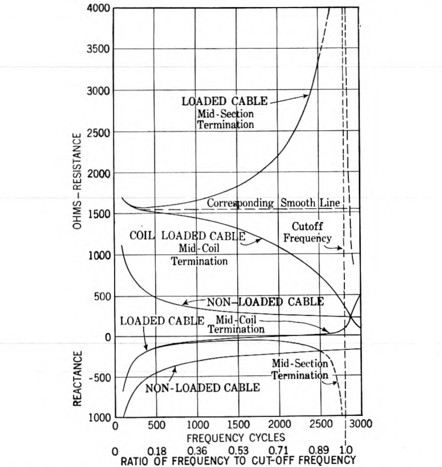
Figs. 1, 2 and 3 illustrate the differences in the attenuation, velocity, and impedance characteristics of a typical telephone cable, with and without loading. The characteristics of the corresponding smooth loaded line are also given to illustrate the theoretical differences between uniform loading and coil loading. Fig. 1 includes curves p. 226 which give an analysis of the different types of line losses, (a) the "series" losses due to heat dissipation in the conductor and the loading coils, which are proportional to the square of the line current, (b) the "shunt" losses due to heat losses in the dielectrics, which are proportional to the square of the line voltage, and (c) the lumpiness effects due to internal reflections. The large reduction in the series losses accomplished by the loading is clearly indicated in the diagram. A corresponding proportional increase in the shunt dissipation loss also occurs, but as previously noted this effect is small in absolute magnitude relative to the decrease in the series losses. It is interesting to note that the particular type of loading illustrated in Fig. 1 so increases the transmission efficiency of No. 19 A.W.G. cable that the loaded circuit can be used for distances about four times the permissible length of the non-loaded circuits. To obtain this increased transmission range without loading would require wires about eight times as heavy, i.e., No. 10 A.W.G.
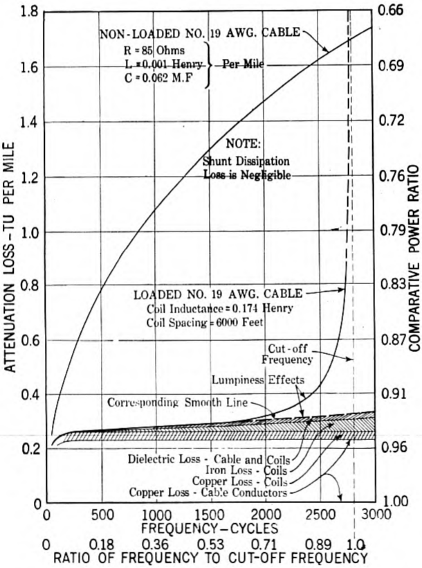
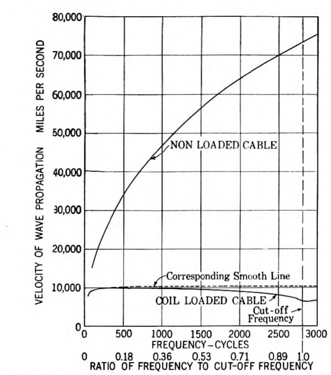
Fig. 3 illustrates the dependency of the characteristic impedance of a coil loaded line upon the terminal condition. The most frequently used loading terminations are "mid-section" and "mid-coil." In the mid-section termination, the first loading coil is located at a distance equivalent to one-half of a regular loading section from the beginning of the line. Mid-coil termination is obtained by installing at the beginning of the line, a coil having one half of the inductance of the regular coils, the first full coil being installed at the end of the first complete loading section. For mid-coil and mid-section terminations, the characteristic impedance is approximately a pure resistance, p. 228 which varies with frequency as a complicated function of the ratio of the frequency to the cut-off frequency. With mid-coil termination the impedance-frequency characteristic droops with rising frequency, approaching zero at the cut-off frequency. On the other hand, the mid-section termination has a rising characteristic, approaching infinity at the cut-off frequency.
Early Standard Loading Systems. One of the fundamental questions involved in the early commercial development work was that of determining what range of frequencies should be transmitted in order to furnish a satisfactory grade of speech transmission. The investigation of this point resulted in the adoption of a standard cut-off frequency of about 2,300 cycles. Table II lists the other important transmission characteristics of the first loading systems standardized about 1904 for use on cables:—
TABLE II
First Standard Cable Loading Systems
| Loading Designation | Coil Inductance (Henrys) | Coil Spacing (Miles) | Inductance per Mile (Henrys) | Nominal Impedance (Ohms) | Attenuation Loss (TU per mile): 19 A.w.g. | 16 A.w.g. | 14 A.w.g. |
|---|---|---|---|---|---|---|---|
| Heavy | 0.250 | 1.25 | 0.200 | 1800 | 0.28 | 0.16 | 0.11 |
| Medium | 0.175 | 1.75 | 0.100 | 1300 | 0.39 | 0.21 | 0.14 |
| Light | 0.135 | 2.5 | 0.054 | 900 | 0.51 | 0.27 | 0.17 |
| (Non-loaded Cable) | 1.05 | 0.74 | 0.59 |
NOTE. These data apply to cables having a mutual capacitance of 0.070 . per mile and assume loading coils, the electrical characteristics of which are given in Table IV. The nominal impedance is defined by the expression . The new unit of transmission loss (TU) is described in a recent Institute paper.6
For open wire loading, only one loading system, known as "Heavy" loading, was standardized. This involved the use of coils having an inductance of 0.265 henry at a spacing of approximately 8 miles. This loading had approximately the same cut-off frequency as the cable loading standards described in Table II. The other important line and transmission characteristics are summarized in Table III.
Loading Coils. The loading coils developed for use in the loading systems described in Tables II and III were of the toroidal type; i.e., they had ring-shaped cores formed by winding up a bundle of insulated p. 229 fine wires on a suitably shaped spool. The core wire was 38 A. w. g. (0.004 in. diameter).
TABLE III
First Standard Open Wire Loading
| Wire Diameter (In.) | Loading Condition | Constants per Loop Mile: Ohms | Henrys | Mf. | Nominal Impedance Ohms | Attenuation Loss TU per Mile |
|---|---|---|---|---|---|---|
| 0.104 | Non-loaded | 10.4 | 0.0037 | 0.0084 | 660 | 0.075 |
| 0.104 | Loaded | 11.1 | 0.037 | 0.0086 | 2100 | 0.031 |
| 0.165 | Non-loaded | 4.14 | 0.0034 | 0.0091 | 610 | 0.033 |
| 0.165 | Loaded | 4.8 | 0.037 | 0.0094 | 2000 | 0.014 |
NOTE. Transmission efficiency figures assume dry weather insulation conditions, 5 megohm-miles, or better.
The wire used in the cable loading coil cores was a commercial grade of mild steel, hard drawn under conditions which gave it an initial permeability of 95. The term "initial permeability" signifies the permeability at very weak magnetizing forces; i.e., below 0.1 gilbert per cm. The core wire used in the open wire loading coils was drawn from the same stock, but differences in the drawing and annealing treatments gave it an initial permeability of about 65. This core wire had lower eddy current and hysteresis losses than the 95-permeability wire. A black enamel insulation was used on the 95-permeability wire. A celluloid-shellac compound which could be applied at a lower temperature was used on the 65-permeability wire.
As illustrating the magnitudes involved, it may be noted that in order to meet the service requirements, the coils were designed so that for telephone currents of the order of 0.001 ampere, the magnetizing force has a value of about 0.04 gilbert per cm., corresponding to a flux density of approximately gauss.
The winding space on the cores was divided in half by means of fiber washers, and the winding was applied in two equal sections, one being located on each half of the core. In installing the coils, one of these windings was inserted in one line wire and the other winding in the other line wire, so connected that the mutual inductance between windings aided the self-inductance for current flowing around the circuit through both windings.
The high costs of the open wire lines warranted considerable refinement in the design of the open wire coils. They were, therefore, made much more efficient and correspondingly larger than the cable coils. They were wound with insulated stranded wire and had much p. 230 lower core losses. Another important difference between the open wire and cable coils was the use of high dielectric strength insulation in the open wire coils. The coils were subjected to a breakdown test at 8,000 volts (effective a-c.) and were protected in service by means of a special type of lightning arrester having non-arcing metal electrodes designed to operate at 3,500 volts direct current.
Table IV lists the principal characteristics of the loading coils initially used in the standard loading systems listed in Tables II and III.
TABLE IV
First Standard Loading Coils
| Type Loading | Coil Code No. | Inductance (Henrys) | Average Resistance: D-C. (Ohms) | 1000-Cycle (Ohms) | Overall Dimensions: Diameter (In.) | Height (In.) |
|---|---|---|---|---|---|---|
| Open Wire | 501 | 0.265 | 2.5 | 5.9 | 9 | 4 |
| Cable | 506 | 0.250 | 6.4 | 22.3 | 4⅛ | 3¼ |
| " | 508 | 0.175 | 4.2 | 13.0 | " | " |
| " | 507 | 0.135 | 3.2 | 9.1 | " | " |
NOTE. Effective resistance values apply for a line current of 0.002 ampere.
Loading Coil Cases. The cases used for potting the cable loading coils were designed so that they could be installed in underground manholes or on pole fixtures.
The general method of assembly is to dry the loading coils thoroughly and then impregnate them under vacuum with a moisture-proofing compound. The coils are then mounted on wooden spindles, adjacent coils being separated by iron washers. After carefully adjusting the individual coils to meet the electrical requirements, the spindles of coils are cabled to a short length of lead-covered cable which is referred to as a "stub" cable. Cast-iron cases with iron partitions were designed so as to provide a shielded compartment for each spindle of coils.
Commercially manufactured toroidal coils may have small irregularities in their windings resulting in a weak stray field which tends to cause cross-talk. The iron washers between coils and the partitions between spindle groups of coils provide effective cross-talk shields.
After placing the spindles of coils in the various compartments, the case is filled with a moisture proofing compound. The lead-sheathed cable stub is brought through a brass nipple in the cast iron cover of the case, and the cover is then bolted to the case. By means of a special design of case and cover joint, a double seal is provided to prevent entrance of moisture at this point. A wiped joint is made between the lead sheath of the cable and the brass nipple.
The conductors in the stub cable have an appropriate color scheme in their insulation to identify the terminals of the loading coils, thus facilitating splicing of the coils into the line circuits. A series of multi-spindle cases was standardized, ranging in capacity from 21 to 98 coils. Smaller quantities of coils were potted in a single spindle pipe type case.
Generally similar assembly and potting methods were used for the open wire coils, the important differences being first, that the open wire coils were always mounted in individual cases designed for mounting on pole fixtures, and secondly, that the coil terminals were brought out of the case in individual rubber-insulated leads.
I. Phantom Group Loading
In Mr. Gherardi's paper reference was made to the development of means for (a) phantoming loaded circuits and (b) loading phantom circuits. The large plant economies made possible by these developments have resulted in extensive applications of these principles.
The following discussion will consider first the coil winding schemes, after which the transmission characteristics of the loading systems and the electrical characteristics of the loading coils will be briefly described.
Loading Methods. Fig. 4 schematically illustrates the Bell System standard method for loading phantom circuits and side circuits of phantoms.7
The loading problem is to introduce the desired inductance into each of the three circuits of a phantom group without causing objectionable unbalances. The method illustrated in Fig. 4 involves individual loading coils for each circuit, the design being such that the side circuit coils are substantially non-inductive to the phantom circuit, while the phantom loading coil is substantially non-inductive to the side circuits. These desirable results require close magnetic coupling between the line windings in each coil. Consequently, in p. 232 p. 233 the side circuit coils each line winding is, in effect, distributed evenly about the entire core. The necessary high degree of symmetry required by balance considerations is obtained by dividing each line winding into two equal sections and interleaving them with the sections of the other line winding; thus each complete line winding consists of an inner section winding on one-half of the core and an outer section winding on the opposite half core. Similar design principles are applied to the phantom loading coils, with added complications, however, arising from the increased number of line windings. Each of the four line windings consists of an inner section winding located on one core quadrant and an outer section winding located on the opposite core quadrant, the two line windings associated with a given side circuit being distributed about the same pair of opposite core quadrants. In arranging the windings on the core, precautions are taken to secure a symmetrical arrangement of the direct admittances among the line windings and from the line windings to the core and the case.
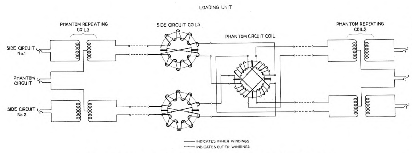
It is interesting to note that the three-coil loading scheme illustrated in Fig. 4 was employed in the Boston-Neponset cable, installed in 1910, which was the first successful installation of loaded phantom circuits in the world. Other schemes of phantom group loading using two-coil and four-coil arrangements have been developed here and abroad, but none of them is considered to be as satisfactory as the scheme illustrated in Fig. 4 from the standpoint of service and cost. These other schemes are described in a recent article8 which compares them with the scheme above described.
Loading Systems. In adapting the circuits to phantom working, the electrical constants of the two-wire circuits were changed as little as possible in making them suitable for use as side circuits of phantoms. In the cables, two pairs having different lengths of twist were twisted into quad formation on a still different length of twist. The required balance was obtained on open wire lines by cutting in a large number of additional transpositions.
The construction methods chosen resulted in the phantom circuits having approximately 60 per cent. greater distributed capacity than their side circuits, and a lower distributed inductance, approximately in inverse proportion. It was obviously desirable to install the phantom circuit coils at the same points as the side circuit coils; accordingly, in working to the same standard of cut-off frequency, the relative circuit constants summarized above resulted in the phantom p. 234 loading systems having a nominal impedance approximately 60 per cent. as high as their associated side circuit loading systems. The transmission efficiency of the phantom circuit was 20 to 25 per cent. better than that of its associated side circuits, on which basis, the phantom circuits were suitable for use over somewhat longer distances than their side circuits.
Cable Loading. Data regarding the general characteristics of the first phantom group loading systems standardized for use on quadded telephone cables are given in the first four rows of Table V. These loading systems were used principally on interurban toll cables. Because of the extra cost of the terminal and signaling equipment, and other factors involved in phantom working, it was not economical to use phantom circuits in the shorter lengths of loaded cable ordinarily involved in exchange area connections.
As soon as the development work on quadded toll cables and phantom group loading had progressed to a point where satisfactory commercial results were assured, active development work commenced on the Boston-New York-Washington cable project, involving the use of coarse gage quadded conductors and new types of high efficiency loading coils designed especially for use on the coarse gage wires. The Boston-Washington cable was the first link in a rapidly growing network of toll cables which now interconnects the large population centers of the Atlantic Seaboard and the upper Mississippi Valley region, providing increased reliability of service as compared with open wire lines.
It should be kept in mind that at the time under discussion (1910–1911) no commercially satisfactory type of telephone repeater was available. Accordingly, in order to assure satisfactory service between Boston, New York, Washington, and intermediate points, it was necessary to provide 10-A.w.g. and 13-A.w.g. conductors in the new cable. Cost studies showed it to be desirable to use a special weight of loading intermediate between the old heavy and medium loading systems, which was therefore designated "Medium-heavy" loading. Information regarding this special loading is given in Items 1 and 2 of Table V. In items 3 and 4, corresponding data are given on the "high-efficiency" heavy loading designed for coarse gage conductors. This heavy loading was used on certain sections of the Boston-Washington cable where plant construction reasons made it desirable to install the coils in existing loading manholes installed at heavy loading spacing.
From the last column of Table V it is seen that there is very little difference between the efficiencies of the heavy and the medium-heavy p. 235 p. 236 loading systems when used on 10-A.w.g. conductors. This explains the more general use of the medium-heavy loading, which was less expensive because of the greater distances between coils. The effects under discussion are due to the part played by the loading coil resistance. The loading coils themselves conformed as closely as practicable to the cost-equilibrium principle:—a condition of cost balance where a small improvement in transmission would require approximately equal expenditure whether by improving the loading or by adding copper to the cable conductors. On this basis, a somewhat less expensive grade of coil was used on the 13-A.w.g. wires than on the 10-A.w.g. wires. The grade of coils developed primarily for use on 16 and 19-A.w.g. cables, giving transmission results illustrated in Items 5–8 of Table V, was in turn less expensive than the "high efficiency" coils. In each case, since the phantom circuits were somewhat more efficient than their associated side circuits, a somewhat higher grade coil was used in the phantom circuits than in the side circuits.
TABLE V
First Loading Standards for Quadded Toll Cables
| Item | Loading Designation | Type Circuit | Coil Inductance (Henrys) | Coil Spacing (Miles) | Nominal Impedance (Ohms) | Attenuation Loss—TU per mile: 19 A. w. g. | 16 A. w. g. | 13 A. w. g. | 10 A. w. g. |
|---|---|---|---|---|---|---|---|---|---|
| 1 | Medium-Heavy | Side | 0.210 | 1.4 | 1500 | 0.085 | 0.050 | ||
| 2 | " " | Phantom | 0.130 | 1.4 | 950 | 0.069 | 0.040 | ||
| 3 | Heavy | Side | 0.250 | 1.25 | 1850 | 0.081 | 0.050 | ||
| 4 | " | Phantom | 0.155 | 1.25 | 1150 | 0.066 | 0.042 | ||
| 5 | Heavy | Side | 0.250 | 1.25 | 1850 | 0.24 | 0.14 | ||
| 6 | " | Phantom | 0.155 | 1.25 | 1150 | 0.20 | 0.12 | ||
| 7 | Medium | Side | 0.175 | 1.75 | 1300 | 0.31 | 0.17 | ||
| 8 | " | Phantom | 0.106 | 1.75 | 800 | 0.26 | 0.14 |
NOTES: A capacitance of 0.062 . per mile is assumed in side circuits and 0.100 . per mile in the phantom circuit. The pair capacitance value is smaller than that assumed in Table II, due to improvement in the cables.
All of the above loading systems have a cut-off frequency of about 2300 cycles.
Open Wire Phantom Loading. Phantom loading came into general use on open wire lines at about the same time as on quadded cables. In general, the methods used in applying phantom group loading to the open wire lines were used for the cable systems. The line characteristics for the side circuits were practically the same as for the original non-phantomed circuits (Table III); the principal difference being that caused by the small resistance of the phantom loading coils. The important linear and transmission characteristics of the phantom circuits are given in Table VI. The phantom loading coil had an inductance value of 0.163 henry.
Loading Coils. Table VII gives general information regarding the first standard side circuit and phantom loading coils used in the phantom group loading systems listed in Tables V and VI. The coils p. 237 designed for open wire lines and for 10-A.w.g. cable had 65-permeability wire cores and stranded copper windings. The coils designed for 13-A.w.g. cables had 65-permeability wire cores and non-stranded copper windings. The other coils had 95-permeability wire cores.
TABLE VI
First Standard Open Wire Phantom Loading
| Wire Diameter (In.) | Loading Condition | Constants per Loop Mile at 1000 Cycles: (Ohms) | (Henrys) | (Mf.) | Nominal Impedance (Ohms) | Attenuation Loss TU per Mile |
|---|---|---|---|---|---|---|
| 0.104 | Non-loaded | 5.2 | 0.0022 | 0.0141 | 400 | 0.064 |
| 0.104 | Loaded | 5.8 | 0.023 | 0.0141 | 1300 | 0.027 |
| 0.165 | Non-loaded | 2.1 | 0.0021 | 0.0154 | 400 | 0.028 |
| 0.165 | Loaded | 2.6 | 0.023 | 0.0154 | 1200 | 0.012 |
TABLE VII
First Standard Loading Coils for Phantom Working
| Type Line | Inductance (Henrys) | Coil Code No. | Type Circuit | Average Resistance-Ohms: D-C. | 1000 cycles | Overall Dimensions: Diameter (In.) | Height (In.) |
|---|---|---|---|---|---|---|---|
| Open-Wire | 0.265 | 512 | Side | 5.0 | 8.4 | 9.0 | 4.0 |
| 0.163 | 511 | Phantom | 2.5 | 4.4 | 11.0 | 4.9 | |
| 10-A. w. g. Cable | 0.210 | 520 | Side | 3.8 | 6.6 | 8.5 | 3.5 |
| 0.130 | 519 | Phantom | 1.9 | 3.4 | 10.4 | 4.0 | |
| 0.250 | 532 | Side | 4.1 | 7.8 | 8.5 | 3.5 | |
| 0.155 | 531 | Phantom | 2.1 | 3.9 | 10.4 | 4.0 | |
| 13-A. w. g. Cable | 0.205 | 538 | Side | 6.0 | 9.2 | 5.7 | 2.5 |
| 0.130 | 521 | Phantom | 3.0 | 4.5 | 7.9 | 3.0 | |
| 0.250 | 534 | Side | 6.6 | 10.7 | 5.7 | 2.5 | |
| 0.155 | 533 | Phantom | 3.3 | 5.3 | 7.9 | 3.0 | |
| 16 and 19-A. w. g. Cable | 0.250 | 515 | Side | 8.9 | 23.1 | 4.6 | 2.4 |
| 0.155 | 530 | Phantom | 4.4 | 11.9 | 5.9 | 2.9 | |
| 0.175 | 514 | Side | 5.4 | 14.4 | 4.6 | 2.4 | |
| 0.106 | 513 | Phantom | 2.7 | 7.1 | 5.9 | 2.9 |
NOTE. The resistance data apply to circuits of a complete phantom group; i.e., the side circuit data include effects of the phantom coils, and phantom circuit data include effects of the side circuit coils. Effective resistance values correspond to line current of 0.002 ampere.
Potting Features. The general practise for cable loading is to pot side circuit and phantom loading coils in the same case as phantom groups, since this has important installation and transmission advantages. The phantom coils, being considerably larger than the side circuit coils, are mounted in separate spindle compartments. The cross-connections between the side circuit and phantom coils are made within the case, in order to reduce the amount of splicing required in the field. Thus, the stub cable contains only the conductors to be spliced to the "east" and "west" conductors in the line cable. Quadded construction is used in the stub cable of all loading coil cases for phantom loading in order to avoid serious capacitance unbalances. p. 238
The multi-spindle cases used in potting the small size coils for 16 and 19-A.w.g. cables ranged in capacity from 12 to 24 phantom units. The larger size coils used on the coarser gage cables were potted in smaller complements.
Occasionally it is desirable to install side circuit loading alone and to install the phantom loading at a later period. Accordingly, cable loading coil cases were designed to meet these conditions. The open wire coils were potted in individual cases.
II. Loading for Repeatered Circuits
General. The development of telephone repeaters to the point where they could be used for commercial service in extending the range of telephone transmission was the beginning of a new era in the communication art. In this development work, the adaptation of the lines to the requirements of repeater operation was secondary in importance only to the development of satisfactory repeater elements and circuits for associating the repeater elements with the line. The reader is referred to an Institute paper by Messrs. B. Gherardi and F. B. Jewett9 for general information regarding telephone repeaters and to a more recent Institute paper by Mr. A. B. Clark10 for a general discussion of subsequent developments in the application of repeaters to long telephone circuits.
The early work on the line problem was primarily concerned with obtaining a sufficiently high degree of regularity in the line impedance-frequency characteristics, so that the requisite high degree of balance could be obtained and maintained between the line and the repeater balancing network. Later on, particularly in preparing for the application of telephone repeaters to long toll cables, such as the New York-Pittsburgh-Chicago cable, it became necessary to change the fundamental transmission characteristics of the loading.
Early Work—Reduction of Line Irregularities. Commercial telephony, requiring two-way transmission, imposes severe balance requirements on repeater circuits over the entire band of frequencies which the repeater is designed to transmit, in order to avoid singing or distortion due to near singing. Within certain limitations, the higher the degree of balance between the line and the balancing network circuit, the higher will be the permissible amplification gain of the repeater.
The practical solution of this fundamental repeater-line balance problem required (a) the construction of lines having extremely regular impedance characteristics over the frequency band which the repeater is designed to transmit and (b) the development of balancing networks11 capable of accurately simulating the sending-end impedance characteristics of the improved lines throughout this frequency range. On account of the great difficulty of getting a high degree of balance at frequencies near the cut-off frequency of the loading, partly due to line irregularity effects and partly due to network design complications, it has been found desirable to use electric wave filters12 in the repeater sets which cut off at a frequency below the cut-off frequency of the loading. This margin of cut-off effects is usually 200 cycles or more, depending upon the repeater design and the type of loading involved.
The "regular" line referred to in (a) is one which is free from impedance irregularities. In the case of loaded lines, the loading coils should have very closely the same inductance values, and the sections of line between loading coils should have closely the same value of capacitance. These uniformity features should be permanent, which requires that the coils should have a high degree of stability in their inductance characteristics; i.e., they should be capable of resisting the magnetizing effects of abnormal service conditions. Some of the older types of coils did not meet this requirement. The satisfactory way in which these fundamental coil requirements are fulfilled in the newer types of coils will be described in a subsequent section.
Uniformity in the loading section capacitance values involves uniformity in cable and line capacitance values as well as precision in the coil spacing. In toll cable loading the maximum deviations from the average spacing are kept below 2 per cent., and the average deviations are in the order of 0.5 per cent. or less.
In exceptional cases where physical obstructions are encountered in reducing the spacing deviations to a sufficiently low value, use is made of "building-out condensers" or "building-out stub cables" to normalize the capacitance of loading sections.13 Abnormally long loading sections can usually be split up into two sections, one or both of which may then be "built out" to the nominal standard capacitance values.
Transcontinental Lines—High Stability Loading Coils. The inauguration p. 240 of commercial transcontinental telephone service over the New York-San Francisco line in January, 1915, marked the first commercial application of these general improvements in regularity of line construction, including the use of an improved type of loading coil.
In the extensive field work which was done in preparing for transcontinental telephone service, it was found that the inductance values of a considerable percentage of the open-wire loading coils then in use (Nos. 511 and 512 types, Table VII) had changed appreciably from the nominal values to which they were adjusted at the factory prior to shipment, and that these changes were due to core magnetization caused by abnormal currents induced by lightning discharges. In some cases abnormal currents induced by power transmission lines or electric railway distribution systems were responsible for the loading coil magnetization.
The inductance changes were not sufficiently large to have serious reactions on transmission over non-repeatered circuits. Although individual coils varied in inductance from time to time, the general average of groups of coils was fairly constant. The effects of these individual variations on the impedance of the line were, however, too large to permit satisfactory operation with telephone repeaters. Some experiments made with improved lightning arresters, in an effort to reduce the coil magnetization trouble, were unsuccessful.
The solution of the problem of repeatering loaded open-wire circuits required the development of loading coils which would be stable magnetically when subjected to extreme conditions of magnetizing current in the windings. The requirement was laid down for these coils that the inductance to speech currents should not be affected more than about 2 per cent. when a magnetizing current of two amperes was passed through either line winding. In view of the fact that the extreme residual magnetizing effect of this current on the No. 511 and No. 512 loading coils was approximately 30 per cent., it will be appreciated that this imposed a very severe stability requirement.
The design adopted involved the use of air-gaps in the cores of the iron wire core loading coils.14 Two air-gaps were employed at opposite points in the cores and suitable clamping means were provided to hold the coil halves in proper alinement. The use of only two air-gaps in the cores of the phantom loading coil brought in unbalance tendencies not present in older designs, which were corrected by special refinements in the design.
The use of a magnetic circuit having "ends," while effective for producing self-demagnetization, brought in troublesome magnetic p. 241 leakage which necessitated special potting methods. Because of the economy of cast-iron loading coil cases, it was decided to continue their use, but to increase their dimensions sufficiently to reduce eddy-current losses in the case to a tolerable point.
The air-gap type loading coils designed for the transcontinental circuits, coded Nos. 549 and 550 for the phantom and side circuits respectively, were more generally potted as phantom loading units than as individual coils, and in such instances the cross-connections between the phantom and side circuit coils were made inside the case. Important advantages of this arrangement were that the leakage losses during periods of low line insulation were greatly reduced as well as the liability of wrong connections of windings during the installation work. Fig. 5 is a photograph of an installation of open p. 242 wire loading coils illustrating both the individual coil and loading unit methods of potting.
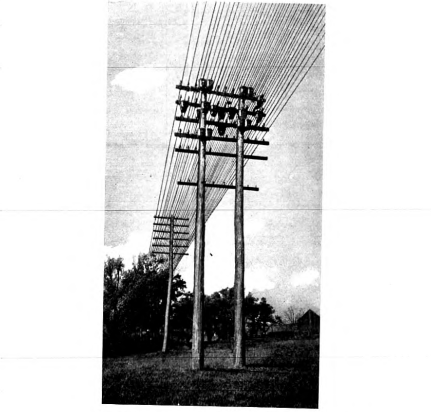
Showing four phantom group (3-coil) cases and nine individual coil cases
Table VIII contains data on the air-gap coils standardized for open-wire circuits. It will be noted that these coils are somewhat less efficient from the standpoint of effective resistance than the older type coils (Nos. 511 and 512) listed in Table VII, though having marked superiority over the latter with regard to magnetic stability. To assist in getting maximum line regularity, the Nos. 549 and 550 coils were adjusted in the factory to meet ± 1 per cent. inductance precision limits. In the older types of coils ± 5 per cent. deviations had been allowed. The nominal inductance values of the Nos. 549 and 550 coils are somewhat below those of the Nos. 511 and 512 coils, the inductance difference corresponding roughly to the average magnetization effect of normal service conditions on the older types of coils.
TABLE VIII
High Stability Coils Having Wire Cores with Air Gaps
| Type Loading | Coil Code No. | Type Circuit | Inductance Henrys | Average Resistance Ohms: D-C. | 1000-Cycles | Overall Dimension Inches: Diameter | Hgt. |
|---|---|---|---|---|---|---|---|
| Open Wire | 550 | Side | 0.245 | 5.4 | 11.1 | 8.1 | 3.9 |
| " " | 549 | Phantom | 0.150 | 2.7 | 6.4 | 10.0 | 4.0 |
| 10 and 13 A. w. g. Cable | 556 | Side | 0.248 | 7.0 | 14.0 | 5.6 | 2.9 |
| 555 | Phantom | 0.154 | 3.5 | 7.0 | 7.5 | 3.6 | |
| 10 and 13 A. w. g. Cable | 558 | Side | 0.200 | 6.2 | 10.9 | 5.6 | 2.9 |
| 557 | Phantom | 0.135 | 3.1 | 5.9 | 7.5 | 3.6 |
NOTES. Open-wire coils used in Loading Systems, Tables III and VI. Cable coils used in Loading Systems, Table V.
Resistance data apply to side circuits and phantom circuits of complete phantom groups. Effective resistance values are for 0.002 ampere line current.
The solution of the transcontinental line problem involved improvements in the regularity of the coil spacing as well as improvements in the magnetic stability of the coils. The line "clearing up" work usually involved a great deal of retransposing, since cross-talk considerations made it necessary to have the coils placed at balanced or neutral points in the transposition layout.
In the case of coarse gage cable circuits, such as the Boston-Washington and other toll cables installed prior to the advent of repeaters, p. 243 the new requirements were met by the design of an air-gap type of wire-core coil on which data are given in Table VIII. They were somewhat smaller and not quite so expensive as the improved open-wire coils.
Compressed Powdered Iron Core Loading Coils. It soon became evident that the economical extension of the toll plant would involve the general introduction of telephone repeaters in cable as well as open-wire circuits. The use of telephone repeaters made it possible to supersede the coarse gage conductors by 16 and 19-A.w.g. conductors for toll connections, and this greatly increased the need for an efficient and stable loading coil of lower cost than the air-gap wire core coil.
As a result of investigations carried on over a period of several years, there was developed for commercial use early in 1916 a new magnetic material, compressed powdered iron, which has been of the utmost value in loading coil design.15 This improved magnetic material is described in a paper presented before the Institute by B. Speed and G. W. Elmen16 which also discusses the electrical and magnetic properties of the material.
Briefly, the method of production consists of grinding electrolytically deposited iron to the desired fineness, insulating the particles of iron, and finally compressing these insulated particles in steel dies at such very high pressures as to consolidate the mass into a ring, the specific gravity of which is substantially equal to that of solid iron. The rings are then stacked in a manner similar to laminations of sheet material to form a core of the desired dimensions. Though the separate rings are approximately 0.2 in. thick, the insulation between the individual particles is so effective that despite the use of molding pressures of 200,000 lb. per sq. in., the eddy current loss in a powdered iron core is less than that obtainable with 0.004 in. iron wire. Depending on the heat treatment and the amount of insulation, the initial permeability can be varied from approximately 25 to about 75. The specific resistance is about 20,000 times that of ordinary iron. The permeability can be controlled within comparatively narrow limits by the manufacturing processes, thus making for greater uniformity. The great advantage of this material for loading coils, however, lies in its self-demagnetizing property. The powdered iron core by virtue of its very numerous, though extremely small distributed p. 244 air-gaps, affords a means for constructing magnetically stable cores without the production of poles and their attendant magnetic leakage.
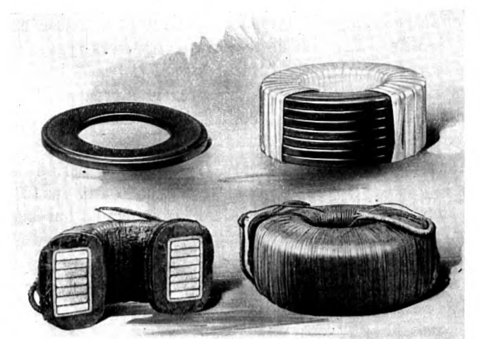
Fig. 6 gives photographs of a standard compressed iron powder core ring such as is used in the cores of toll cable loading coils; a completely assembled core with part of the core taping removed; a completely wound coil of the side circuit type; and a coil in cross-section. Table IX gives general data regarding typical coils.
The first application of powdered iron cores was to replace some of the 95-permeability wire core loading coils in 16 and 19-A.w.g. cable. The effective permeability of the 95-permeability wire cores, making correction for air spaces and insulation, was approximately 60, and accordingly, the replacing powdered iron cores were designed to have the same effective permeability.
As a result of further developments in the direction of applying vacuum tube repeaters to loaded cable circuits, it became necessary with the extension of the length of these circuits to improve the characteristics of the loading coils. This led to the development of an improved grade of powdered iron core having an initial permeability of 35 which corresponds closely to the effective permeability of cores using iron wire having a permeability of 65. It was decided that for circuits such as interoffice trunks and short cables which would not be operated with superposed telegraph, the 60-permeability compressed iron core coils should be used; while for toll cable work p. 245 involving repeatered composited circuits, 35-permeability cores should be employed. All of the compressed powder core coils intended for repeatered circuits were adjusted to meet ± 2 per cent. inductance limits.
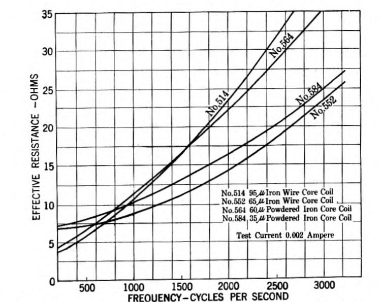
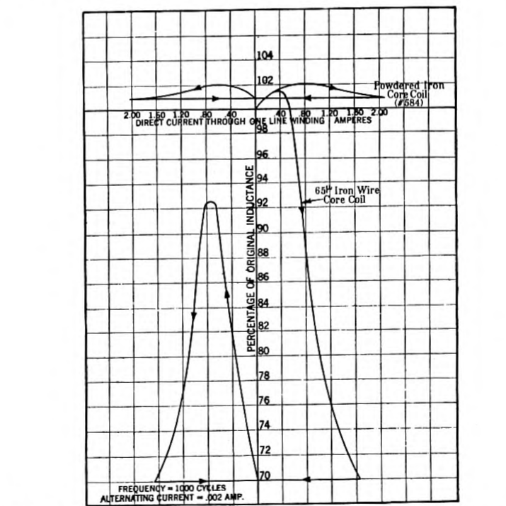
The effective resistance-frequency characteristics of 95-permeability and 65-permeability wire core coils and 60-permeability and 35-permeability powdered iron core coils having the same inductance (0.174 henry) and the same over-all sizes are given in Fig. 7. The large improvement as to freedom from residual magnetization effects afforded by the 35-permeability powdered iron core, compared with the 65-permeability wire core is evident from the curves of Fig. 8. The effective resistance and inductance variation with current strength are shown in Fig. 9 for a 35-permeability powdered iron core coil. The remarkable property of these cores of maintaining constancy of permeability is shown by the change of only 1 per cent. in permeability as the current strength varies 400 per cent. from, say 0.001 to 0.005 ampere.
It is interesting to note that after the process had been fully worked out and production was running on a commercial scale, the cost of the improved cores was comparable with that of the wire cores which they replaced.
TABLE IX
Typical Compressed Powdered Iron Core Loading Coils
| Coil Code No. | Core Permeability | Inductance (Henrys) | Type Circuit | Resistance Ohms: D-C. | 1000-Cycles | Dimensions Inches: Diameter | Height |
|---|---|---|---|---|---|---|---|
| 562 | 60 | 0.245 | Side | 11.4 | 25.8 | 4.5 | 2.1 |
| 561 | 60 | 0.155 | Phantom | 5.7 | 11.7 | 6.3 | 3.0 |
| 564 | 60 | 0.174 | Side | 6.6 | 15.4 | 4.5 | 2.1 |
| 563 | 60 | 0.106 | Phantom | 3.3 | 6.7 | 6.3 | 3.0 |
| 582 | 35 | 0.245 | Side | 15.9 | 21.8 | 4.7 | 2.4 |
| 581 | 35 | 0.155 | Phantom | 8.0 | 10.0 | 6.7 | 3.1 |
| 584 | 35 | 0.174 | Side | 10.8 | 14.1 | 4.7 | 2.4 |
| 583 | 35 | 0.106 | Phantom | 5.4 | 6.6 | 6.7 | 3.1 |
| 584 | 35 | 0.174 | Side | 12.1 | 15.3 | 4.7 | 2.4 |
| 587 | 35 | 0.063 | Phantom | 6.1 | 7.0 | 4.7 | 2.8 |
| 590 | 35 | 0.044 | Side | 4.0 | 4.6 | 4.7 | 2.4 |
| 591 | 35 | 0.025 | Phantom | 2.0 | 2.0 | 4.7 | 2.8 |
NOTE. Resistance values apply to side circuits and phantom circuits of complete phantom groups. Effective resistance corresponds to 0.002-ampere line current.
These coils are used in the loading systems listed in Tables V and X. p. 246
In connection with the development of the new core material which was undertaken as a part of the loading coil development program, an enormous amount of work was involved which would not ordinarily be associated with loading coil design work. For instance, there were undertaken chemical studies on electro-deposition of iron and methods of insulating the iron particles, metallurgical studies of the production of finely divided iron by various means, refinements in shielded electrical measuring equipment for accurate determination of small core losses at voice frequencies, development of special permeameters to make possible the rapid determination of the permeability of rings, the design of the steel moulding dies, selection of suitable grades of alloy steel to withstand the enormous pressures, and also various other special problems. These are mentioned here as illustrative of the scope of the problem of developing this new core material.
It is of interest to note that the compressed powdered iron core loading coil has been adopted also as the international standard in Europe for repeatered circuits.17
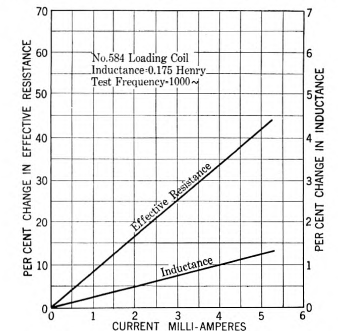
Fig. 9—Variation of Inductance and Effective resistance
With line current in 35-permeability compressed powdered iron core loading coil
p. 248
New Requirements for Cable Loading Systems. In the first commercial applications of telephone repeaters, the new features in the loading were the improved types of coils already described and the improved precision of spacing the coils. No fundamental changes were made in the loading systems then standard.
The completion of the development of a satisfactory commercial type of telephone repeater marked the beginning of a long period of experimental work for the purpose of determining the commercial possibilities of the use of repeaters over long cable circuits. When loaded cables of improved impedance regularity became available, long circuits were built up for experimental purposes by looping back and forth. As the length of these circuits was increased, phenomena not previously observed in cable circuits became increasingly troublesome, and it became apparent that it would be necessary to develop new loading systems having improved velocity and higher cut-off frequency characteristics in order to realize the full possibilities of repeaters in extending the range and reducing the cost of long distance telephone service over cables.
The disturbances above mentioned were found to be due to:
(a) Echo effects.
(b) Velocity distortion.
These phenomena originate in the lines themselves and are made more apparent by the amplifying action of the repeaters. They are present in non-repeatered circuits but not to a noticeable degree. It is the combination of the extreme length of the circuit and the use of repeaters to keep the over-all loss low that makes the disturbances troublesome.
Echoes. Echoes are due to unbalance currents; i.e., to the reflection of electrical energy at points of impedance irregularity in the circuits. When the circuit is so long that the time of transmission from the point of reflection to the disturbed subscriber is appreciable, there will be echo effects unless the losses in the circuit are so large as to cause the reflected energy to become inappreciably small. On such circuits it may be necessary to work the repeaters at gains well below those at which "singing" occurs or distortion due to "near singing" is experienced.
Since the time of transmission is such an important factor in echo phenomena, reductions in the harmful effects of these disturbances have been obtained in the improved loading systems which have been developed for use on long repeatered circuits, by substantially increasing the velocity of transmission. Recently there has become p. 249 commercially available a device known as an "echo suppressor" which interrupts the path of the echoes without disturbing the main transmission. A description of the device and its field of application was given in a recent Institute paper.18
Velocity Distortion. In a coil loaded line the steady state velocity of wave propagation varies with frequency. At the upper frequencies the velocity change is principally due to lumpiness effects of the loading and is, therefore, a function of the ratio of the frequency under consideration to the cut-off frequency. As illustrated in Fig. 2, the departure of the actual velocity from the nominal velocity of the corresponding smooth line () increases as the frequency is raised, the rate of change increasing rapidly as the cut-off frequency is approached. At frequencies below approximately 0.3 of the cut-off frequency the coil loaded line has substantially the same velocity characteristics as the corresponding smooth line; when the frequency is further reduced, the departure of the actual velocity from the nominal velocity increases as a function of the ratio of the line resistance to the inductive reactance per unit length.
As a result of these velocity-frequency relations, a long loaded repeatered circuit may have seriously objectionable quality, even when the attenuation-frequency distortion is made negligible by the use of special devices at the repeater stations for correcting the attenuation-frequency distortion effects.
The velocity distortion is particularly noticeable during the building-up and dying-down periods, when it manifests itself as transient distortion. The duration of transient distortion depends, among other factors, upon the length of the line, the nominal velocity, and the cut-off frequency of the loading. In the old standard loading systems the high frequency velocity distortion caused by the lumpiness effects of the loading was more serious than the low frequency velocity distortion. Accordingly, a substantial reduction in the transient distortion has been obtained in the new standard loading systems by raising the cut-off frequency of the loading.
For further discussion of velocity distortion reference should be made to Mr. A. B. Clark's paper,19 previously mentioned, which gives experimental results and to an earlier Institute paper by Mr. J. R. Carson20 which gives the results of theoretical studies. p. 250
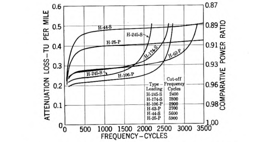
Characteristics of Improved Cable Loading Systems. The principal electrical features of the H-44-25 and H-174-63 phantom group loading systems which have been developed primarily for use on long repeatered cables are given in Table X. Corresponding details of the older standard loading system developed for non-repeatered cables are also included in this table. Typical attenuation-frequency curves of the old and new loading systems are given in Fig. 10.
In the following discussion of detailed characteristics, the various phantom group loading systems will be referred to in terms of recently standardized designations which include a letter to symbolize the coil spacing, in combination with two numbers which correspond with the effective coil inductance values in milhenrys, the first number referring to the side circuit coils and the second number to the phantom coils. The individual side circuit or phantom circuit loading systems have designations which include a letter to symbolize the coil spacing, coupled with the inductance value of the loading coils in milhenrys, and having a letter suffix "" or "" indicating the type of circuit, side or phantom.
The fundamental differences between the new and the old loading systems are with respect to velocity of wave propagation and cut-off frequency, these changes having been made in accordance with the preceding discussion primarily for the purpose of reducing echo effects and transient distortion. For reasons of plant economy and p. 251 p. 252 flexibility, the new loading systems all have the same coil spacing of 6,000 feet.
TABLE X
Loading Systems—Small Gage Repeatered Toll Cables
| Item | (a) Loading System | Circuit | (b) Coil Code No. | Nominal Impedance (Ohms) | Nominal Cut-off Frequency (Cycles) | Transmission Velocity Miles per Second | (c) Attenuation Loss TU per Mile at 1000 Cycles: 19 A. w. g. | 16 A. w. g. | (d) Maximum Geographical Length (Miles) |
|---|---|---|---|---|---|---|---|---|---|
| (1) | H- 44-25 | Side | 590 | 800 | 5600 | 19000 | 0.48 | 0.25 | 5000 |
| (2) | " | Phantom | 591 | 450 | 5900 | 20000 | 0.40 | 0.21 | 5000 |
| (3) | H-174-63 | Side | 584 | 1550 | 2800 | 10000 | 0.28 | 0.16 | 500 |
| (4) | " | Phantom | 587 | 750 | 3700 | 13000 | 0.28 | 0.16 | 1500 |
| (5) | H-174-106 | Side | 584 | 1550 | 2800 | 10000 | 0.28 | 0.16 | 500 |
| (6) | " | Phantom | 583 | 950 | 2900 | 10000 | 0.22 | 0.13 | 500 |
| (7) | H-245-155 | Side | 582 | 1850 | 2400 | 8000 | 0.25 | 0.16 | 250 |
| (8) | " | Phantom | 581 | 1150 | 2400 | 8000 | 0.20 | 0.12 | 250 |
NOTES: (a) Nominal coil spacing is 6000 feet in cable having a capacitance of 0.062 /mile in the side circuits and 0.100 /mile in the phantom circuits.
(b) The loading coil data are given in Table IX.
(c) These attenuation values apply at 55 deg. fahr. Under extreme temperature conditions, the actual attenuation may be approximately 12 per cent larger or smaller, due principally to changes in conductor resistance with temperature. In long repeatered cable circuits these variations of attenuation with temperature require special corrective treatment by means of automatic transmission regulators. (Reference No. 10.)
(d) These length limitations are set by transient distortion effects; echo currents may limit circuit lengths to lower values, depending on the grade of balance of the lines and the permissible over-all loss.
The coil spacing being fixed, it necessarily follows that any reduction in coil inductance for the purpose of raising the cut-off frequency will also increase the transmission velocity. The attenuation improvement obtained by the loading decreases as the velocity is increased. High velocity loading is more expensive than low velocity loading, in the sense that more repeaters are required for the same over-all loss. Obviously, although high velocity loading could be used for short haul traffic, it would not be so economical as a low velocity loading. Commercial considerations thus justify a series of loading standards, graded to meet the requirements of the different lengths of circuits.
At the present time the two phantom group loading standards, H-44-25 and H-174-63, are sufficient to meet the graded requirements of commercial toll cable circuits, when used with suitable combinations of conductor sizes and repeaters. Three different general types of repeaters are used, known as the 21, 22, and 44 types.21 The 21 type is used on two-wire circuits requiring only one repeater, under conditions where switched connections involving other repeaters are not involved. The 22 type is used on two-wire circuits requiring one or more repeaters. The 44 type is used on four-wire circuits, where one pair of wires is used for one-way transmission in one direction and the other pair of wires for transmission in the opposite direction. When phantom circuits are worked on a four-wire basis, each one-way transmission path actually uses four wires.
Table XI lists the combinations of loading, conductor gage, and type of repeater circuit which are used in meeting the wide range of commercial requirements. The position of the facility item in the table indicates the sequence of transmission excellence, Item (i) being the highest grade facility in this respect. In general, the cost of these facilities is in reverse order to the sequence of electrical excellence.
The exact limits of the field of use of a given type of facility depend upon the magnitude of the permissible over-all transmission loss, and upon the grade of repeater balance obtainable. A discussion of these features would bring in complicated engineering questions beyond the scope of the present paper. So far as loading features are concerned, it is sufficient to state that H-44-25 loading is generally used on circuits of approximately 500 miles or more. On circuits intended for switched business, it is frequently necessary to use this p. 253 type of loading for much shorter distances. For further discussion of the use of repeatered loaded lines reference is made to recent papers presented before the Institute by Mr. J. J. Pilliod22 and Mr. H. S. Osborne.23
TABLE XI
Types of Toll Cable Facilities
| Item No. | Length Circuit | Cable Gage | Type of Loading | Type Circuit | Type Repeater |
|---|---|---|---|---|---|
| (a) | (short) | 19 | H-174-63 | 2-wire | — |
| (b) | 16 | " | " | — | |
| (c) | 19 | " | " | 21 | |
| (d) | 16 | " | " | 21 | |
| (e) | 19 | " | " | 22 | |
| (f) | 16 | " | " | 22 | |
| (g) | 19 | " | 4-wire | 44 | |
| (h) | 16 | H- 44-25 | 2-wire | 22 | |
| (i) | (very long) | 19 | " | 4-wire | 44 |
H-63-P versus H-106-P Loading. The standardization of the H-63-P loading to replace the H-106-P loading for association with H-174-S loading, is of particular interest in illustrating the reactions of repeater requirements on loading design. Phantom circuits necessarily have a lower attenuation constant than the associated side circuits, when the loading is designed to meet the same standard of cut-off frequency and the coils are spaced at the same loading points. When repeaters are used on such loaded phantom circuits, the net equivalent is practically no lower than the net equivalent of the associated side circuits, due principally to the fact that the loaded sides and phantoms have practically the same velocity and cut-off frequency characteristics.
Under present operating conditions for short small gage loaded circuits of such lengths that satisfactory transmission results can be obtained without using telephone repeaters, there is ordinarily no important advantage in having the phantom circuit more efficient than the side circuits. It is a distinct operating convenience, of course, to be able to use the phantom circuit and its associated side circuits indiscriminately for the same class of service.
Having the above situations in mind, it was decided to redesign the phantom loading so that it would have approximately the same p. 254 attenuation constant at 1,000 cycles as the associated H-174-S loading. This resulted in the reduction of the phantom loading coil inductance to 63 milhenrys. On the basis of equal attenuation losses in the phantom circuit and its side circuits, the continued use of a higher grade coil in the phantom circuit was no longer justified from a cost standpoint. Accordingly, the new 63-milhenry phantom coil (Code No. 587, Table IX) was designed to have approximately the same d-c. resistance as the earlier standard 106-milhenry coil (Code No. 583), since this permitted a substantial reduction in the size of the loading coil and a consequent reduction in cost, without increasing the over-all losses in the associated side circuits. The design finally chosen resulted in the phantom coil having approximately the same over-all dimensions as the associated side circuit coils. This permitted the phantom coils to be mounted on the same spindles with the associated side circuit loading coils as phantom groups, thus reducing the amount of inside cabling. This gave improved electrical results, besides reducing the potting costs. The use of the smaller size phantom coil, in combination with a larger size case, made it practicable to pot a total of 45 phantom group combinations (135 coils) in a single case. Using the same size case for potting phantom group combinations involving the older large size phantom coils, the limit on the number of coils was 108 (36 phantom groups).
The reduction of the phantom coil inductance from 106 to 63 milhenrys made a substantial increase in the cut-off frequency and in the velocity of transmission, as noted in Table X. These improved characteristics made the H-63-P circuit much superior to the H-106-P circuit from the standpoint of echoes and velocity distortion characteristics. On this basis the H-63-P circuit is intermediate in transmission excellence between H-174-S and H-44-25 circuits.
It was found inadvisable to make a similar change in the H-44-25 loading system owing to cross-talk reactions following from the necessary use of higher repeater gains in the phantom circuit. These undesirable reactions, though present to a lesser degree in the case of the H-174-63 system were offset by the factors already described. The size of the H-25-P coil was, however, reduced to comform to the potting method adopted for H-174-63 loading.
From the standpoint of repeater circuits the H-174-63 system is inherently better than the H-245-155 system because of its higher velocity and higher cut-off, with resulting higher quality of transmission. Furthermore, as far as non-repeatered circuits are concerned, there is a negligibly small difference between the transmission performances, considering frequency distortion effects as well as volume p. 255 efficiency effects. The standardization of the H-174-63 phantom group loading system, therefore, marked the abandonment of use in new facilities of the old standard H-245-155 phantom-group loading system.
Attenuation—Frequency Distortion. In addition to their improved velocity and cut-off frequency characteristics, the H-44-25 and H-174-63 loading systems have an important advantage from the standpoint of attenuation-frequency distortion effects, as is illustrated in Figs. 10 and 11. The frequency distortion effects illustrated in Fig. 10 may become very serious in very long lines. An indication of this is given in Fig. 11. The heavy line curves in this diagram illustrate the attenuation-frequency characteristics of a 500-mile 19 A.w.g. cable circuit involving the various types of loading noted, assuming that "perfect repeaters" are used in each case to reduce the total line loss to 10 TU at 1,000 cycles. The foregoing "perfect repeater" is assumed to have the same amplification at all frequencies. Of course, in order to have the same over-all efficiency in the different types of circuits at 1,000 cycles, it is necessary to assume different total amounts of repeater gain. The dotted lines in Fig. 11 illustrate corresponding frequency characteristics of short non-repeatered cables having the same types of loading as before; in each case the length of 19 A.w.g. cable circuit being chosen so that the non-repeatered circuits have the same loss (10 TU) at 1,000 cycles. A visual inspection of the dotted and heavy line curves indicates how the line losses pile up in long connections. In the old standard low cut-off loading, the accumulated losses in very long lines amount to a suppression effect for frequencies above 1,600 cycles.
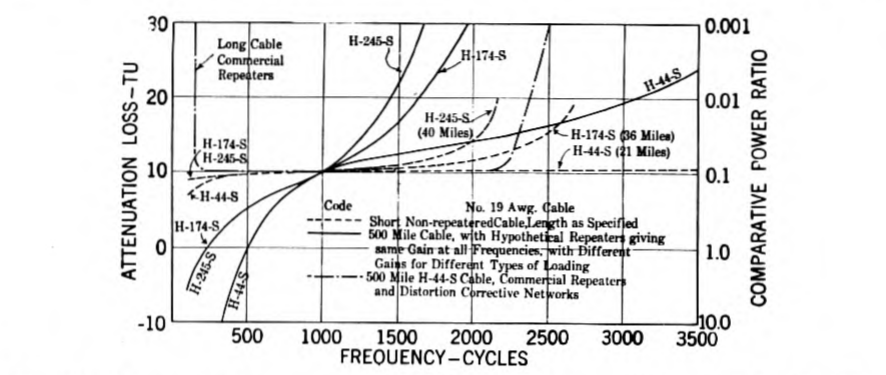
Fig. 11—Attenuation-frequency characteristics of short and long loaded toll cable circuits having a net attenuation loss of 10 TU at 1000 cycles p. 256
In very long lines having the newer grades of loading, the line losses are still sufficient to cause serious attenuation distortion effects if allowed to go uncorrected. The improved types of repeaters now used on long loaded circuits provide somewhat higher gains at the upper speech frequencies, thereby obtaining approximately a flat frequency characteristic over a wider frequency range. In repeaters used in conjunction with the H-44-25 loading, losses are introduced at the lower speech frequencies by auxiliaries to the repeater circuit, for the purpose of flattening the frequency characteristic at low frequencies. An indication of the improvement obtainable in the above ways is given by a dot-dash curve in Fig. 11, which illustrates the attenuation-frequency characteristic of a 500-mile H-44-S circuit having the best types of repeaters now commercially available.
In view of the difficulties brought into repeatered circuits by the use of loading, the question comes up: "Why not use more repeaters and do without the loading?" In the case of long cable circuits the answer to this question is that the coil loading substantially improves the attenuation and substantially reduces the frequency distortion at a cost which is much lower than the cost of the additional repeaters and distortion corrective networks which would be required to give the same grade of transmission without using loading.
Long Repeatered Open Wire Lines. In the case of the long open wire lines, the present day answer to the foregoing question is unfavorable to the use of loading. The use of improved types of repeaters now makes it possible to secure better transmission results in long repeatered circuits without loading, than can be secured in loaded repeatered lines. In this connection it should be noted that in the case of non-loaded open wire lines the distributed inductance is sufficiently large to keep the attenuation-frequency distortion low. Also the velocity of transmission is very high relative to that of a coil loaded line and there is no cut-off effect except that produced by the filters and other apparatus in the repeater sets.
These general transmission considerations are resulting in the removal of coil loading from high grade open wire lines. This dismantling work is being accelerated in order to adapt the open wire plant for a much more extensive application of carrier telephone and carrier telegraph systems.
The present expectations are that in the future new applications of open wire loading will generally be limited to isolated cases of short lines where carrier telephone or telegraph systems are not contemplated and where the maintenance and operating conditions are unfavorable to the use of telephone repeaters. p. 257
Cable Loading Installation Features. Cost considerations make it desirable to use aerial cable in the long toll cable installations, so this type of construction is generally used in the open country. In the vicinity of large population centers, underground cable is used.
Typical aerial cable loading installations are illustrated in Figs. 12 and 13. On the main trunk cables two-pole fixtures capable of supporting four to six large coil cases are usually required. Fig. 12 illustrates a fixture of this type designed for supporting four cases, three of which are already in place. On the smaller branch cables a single pole fixture such as illustrated in Fig. 13 is commonly used.
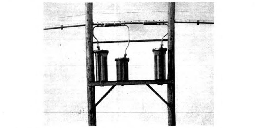
At the time a toll cable is installed, provision is made in the cable splices for the ultimate requirements as well as for the initial loading installation. Ordinary splices are made for the coils which are installed at the time the cable is placed, and "balloon" splices which provide the slack wire required for splicing are arranged for subsequent installations.
III. Loading for Incidental Cables in Open Wire Lines
In the loading applications discussed in the preceding sections, the primary purpose of the loading is to reduce line attenuation losses and frequency distortion effects. In the case of incidental pieces of cable in open wire lines, however, the primary function of the loading is to give the inserted cable approximately the same impedance characteristics as the open wire line, in order to minimize reflection effects p. 258 at the junction of the cable and the open wire construction. An incidental cable occurring at a line terminal is ordinarily known as a toll entrance or a terminal cable; when occurring at an intermediate point, it is known as an intermediate cable.
The reduction of junction impedance irregularities has become especially important during recent years as a result of the rapidly increasing use of telephone repeaters, since in repeatered circuits, line impedance irregularities, by virtue of their effect upon the repeater circuit balance, may reduce the effective repeater gain and thereby impair transmission by an amount much larger than the ordinary reflection loss. Prior to the general use of telephone repeaters, satisfactory results were obtained by using some one of the standard heavy or medium weight cable loading systems on the entrance and intermediate cables associated with loaded open wire lines, and a special weight of loading was used on the incidental cables in the non-loaded open wire lines. In some cases ordinary medium loading was used, with suitable types of step-up or step-down transformers at the terminals of the inserted cable.
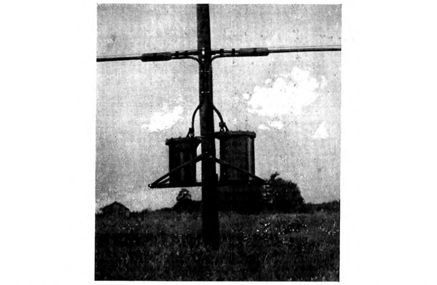
Incidental Cables in Loaded Open Wire Lines. In toll entrance and intermediate cables associated with loaded open wire lines, the p. 259
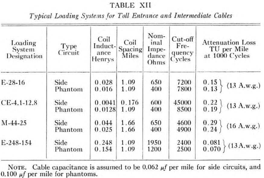
primary requirements for matching impedance are that the nominal impedance and the cut-off frequency of the cable loading and of the loaded open wire line should be closely the same. To a first degree of approximation this means that the cable loading sections should have the same total mutual capacitance as the open wire loading sections, which, of course, requires a very much closer spacing. The cable loading system which was standardized for use in association with loaded open wire lines is designated "E-248-154". Its primary electrical characteristics are given in Table XII. Besides meeting the impedance requirements for use in association with repeatered open wire lines, it is also very satisfactory with respect to attenuation characteristics. In placing this loading, it is customary to locate the first loading point in the cable at such a distance from the last loading point in the open wire line that the total capacitance of the junction loading section is closely the same as that in the regular open wire loading sections.
TABLE XII
Typical Loading Systems for Toll Entrance and Intermediate Cables
| Loading System Designation | Type Circuit | Coil Inductance Henrys | Coil Spacing Miles | Nominal Impedance Ohms | Cut-off Frequency Cycles | Attenuation Loss TU per Mile at 1000 Cycles | (gage, braced over the pair) |
|---|---|---|---|---|---|---|---|
| E-28-16 | Side | 0.028 | 1.09 | 650 | 7200 | 0.15 | (13 A.w.g.) |
| Phantom | 0.016 | 1.09 | 400 | 7800 | 0.13 | ||
| CE-4.1-12.8 | Side | 0.0041 | 0.176 | 600 | 45000 | 0.22 | (13 A.w.g.) |
| Phantom | 0.0128 | 1.09 | 400 | 8500 | 0.19 | ||
| M-44-25 | Side | 0.044 | 1.66 | 650 | 4600 | 0.29 | (16 A.w.g.) |
| Phantom | 0.025 | 1.66 | 400 | 4900 | 0.24 | ||
| E-248-154 | Side | 0.248 | 1.09 | 1950 | 2400 | 0.081 | (13A.w.g.) |
| Phantom | 0.154 | 1.09 | 1200 | 2500 | 0.070 |
NOTE. Cable capacitance is assumed to be 0.062 per mile for side circuits, and 0.100 per mile for phantoms.
Incidental Cables in Non-Loaded Open Wire Lines. The problem of designing coil loading for incidental cables in non-loaded open wire lines is considerably more complicated than the case above discussed, primarily because it involves an impedance match between a smooth line and a lumpy line. Broadly stated, the first part of the problem is to design a loaded cable of such characteristics that its p. 260 corresponding smooth line is closely similar to the non-loaded open wire line. The second and more complicated part of the problem is to determine the coil spacing. This usually involves some degree of compromise, because of the dependence of the impedance of a loaded cable upon the loading termination.
The first general requirement is that the ratio of inductance to capacitance to resistance per unit length in the loaded cable should be the same as the corresponding ratio in the non-loaded open wire line. Ordinarily, the loading coil resistance does not play an important part in the determination of the optimum resistance for the loaded cable, the choice of conductor gage being far more important. From this point of view, No. 13 A.w.g. is practically the best gage of conductor for entrance cable circuits connecting with 165-mil open wire lines. For the optimum impedance match on cables connecting with 104-mil open wire lines, it is necessary to use much higher resistance conductors, the choice between Nos. 16 and 19 A.w.g. conductors depending upon a number of factors which space limits do not allow to be discussed.
As noted in the discussion under "Theory" in the first part of the paper, the characteristic impedance of a uniform line is substantially a pure resistance, having the value over the frequency range throughout which the inductive reactance per unit length is large with reference to the resistance. On the other hand, the characteristic impedance of a coil loaded cable varies over a wide range with frequency, depending upon the particular loading termination used.
Typical impedance-frequency curves for mid-coil and mid-section terminations are illustrated in Fig. 3. As will be seen from this diagram, the rising slope of the mid-section termination and the drooping slope of the mid-coil termination do not deviate greatly from a straight line relation for frequencies below approximately 0.5 of the cut-off frequency. The higher the cut-off frequency is, the more closely will the impedance-frequency characteristic of the loaded cable approach the flat characteristic of the non-loaded open wire line over the range of frequencies involved in speech transmission. In this connection, it is to be noted that the repeaters now used on open wire lines are designed to transmit frequencies between approximately 200 and 2,600 cycles. Of course, the higher the cut-off frequency, the more expensive will be the loading. Practical reasons make it desirable to space the loading coils on the cable circuits connecting with non-loaded open wire lines at the same intervals as the coils which are used on the cable circuits connected with the loaded open wire lines. This consideration in combination with the nominal impedance p. 261 requirement previously mentioned, fixes the cut-off characteristics and, hence, the slope of the termination impedance-frequency characteristic.
These general considerations have led to the standardization of the E-28-16 loading system for use on entrance cable and intermediate cable conductors associated with non-loaded open wire lines. General data for this system are given in Table XII, and the computed impedance characteristics are illustrated in Fig. 14, which also gives the characteristic impedance curves for the non-loaded open wire line and the non-loaded cable. Since the E-28-16 loading system is a low impedance loading, the attenuation improvement is small relative to that of other types of loading system which are primarily installed for attenuation improvement.
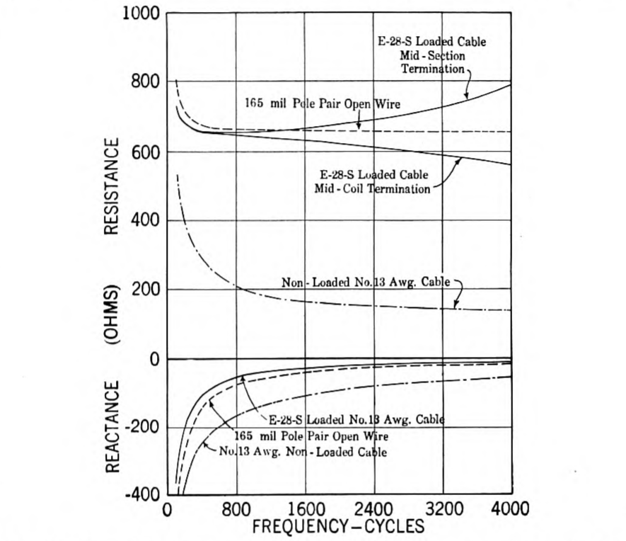
Table XII also gives general data regarding the M-44-25 entrance cable loading system which has been used to some extent as a substitute for the E-28-16 loading system on cables connected to non-loaded open wire lines. The M-44-25 system used higher inductance p. 262 loading coils and considerably longer spacing intervals than the E-28-16 system, and was consequently less expensive. The impedance characteristics, however, were not so satisfactory at the upper speech frequencies because of the greater slope of the impedance-frequency characteristic, due to the lower cut-off.
Carrier Frequency Loading. Special types of entrance cable loading have been developed for use on incidental cables in open wire lines on which carrier telephone or carrier telegraph systems are superposed. Loading system CE-4.1-12.8 listed in Table XII exemplifies this type of loading. The present standard carrier telephone systems operate up to frequencies of the order of 30,000 cycles.24
In order to get satisfactory impedance and attenuation characteristics in the loaded incidental cables, a cut-off frequency of approximately 45,000 cycles is used.
The highest working frequency in carrier loaded cables is approximately 0.75 of the cut-off frequency. The ordinary mid-coil and mid-section terminations do not give sufficiently close approximations to a flat impedance-frequency characteristic over this wide range of frequencies, so it has been necessary to use at the terminals of carrier loaded cables, a simple impedance corrective network.
Data regarding attenuation losses in a typical carrier loaded cable are given in Table XIII. For purposes of comparison similar data are given on a corresponding non-loaded cable. Effective resistance values of the carrier loading coil are also included.
The high frequency loading is used only on the side circuits, since at the present time it is not customary to operate carrier telephone systems over phantom circuits. The associated phantom circuit p. 263 loading is designed for ordinary speech transmission. In order to transmit the high frequency carrier currents over the side circuits, it is necessary to have the side circuit loading coils spaced much more closely than for the ordinary voice frequency loading coils in the phantom circuit. On this account the theoretically best loading points for the carrier circuits frequently occur at places where it is inconvenient to locate the loading coils. The actual loading sections in such cases are made shorter than the theoretical lengths, and the deficiencies in loading section capacitance are remedied by adding lumped capacitances in the form of "building-out condensers." Recently, special types of stub cable designed specially for building out purposes have come into use as substitutes for building-out condensers.
TABLE XIII
Carrier Frequency Loading
| Frequency Kilocycles | Attenuation Loss-TU per Mile (13 A. w. g. Cable): Non-Loaded | C-4.1 Loading | Resistance-Ohms per Carrier Loading Coil |
|---|---|---|---|
| 1 | 0.49 | 0.23 | 1.5 |
| 5 | 0.78 | 0.27 | 1.6 |
| 10 | 0.90 | 0.33 | 1.9 |
| 20 | 1.14 | 0.52 | 4.1 |
| 30 | 1.37 | 0.90 | 8.1 |
Loading Coils. The design of the coils used in the E-28-16 and M-44-25 loading systems is generally similar to the toll cable loading coils having 35-permeability compressed powdered iron cores already described. The loading coils used in the E-248-154 loading system are larger coils of the air-gap type 65-permeability wire core construction listed in Table VII.
As regards the carrier loading system, CE-4.1-12.8, since this involves the transmission through the loading coils of frequencies up to 30,000 cycles or somewhat higher, special coil designs are required. The coil which loads the audio frequency phantom circuit, aside from being specially balanced for association with the side circuit coils, is generally similar in construction to the compressed powdered iron core phantom coil for toll cables.
The side circuit coil, however, is used for loading the high frequency circuit, and more severe requirements are, therefore, imposed on it owing to the multi-frequency transmission. Ordinarily the circuits are equipped to provide three or four carrier telephone channels or 10 carrier telegraph channels over a pair of wires, in addition to the ordinary audio frequency telephone and grounded telegraph channels. The primary added requirements as regards the loading coils are freedom from intermodulation between channels, and low energy losses at carrier frequencies. The most satisfactory solution as regards freedom from magnetic modulation is the avoidance of the use of ferro-magnetic core materials. The side circuit loading coils were, accordingly, designed as toroidal wood core coils, with finely stranded copper windings in order to limit the eddy-current losses. Data regarding resistance-frequency characteristics are included in Table XIII.
The air core side circuit coils have a small leakage inductance which must be allowed for in determining the phantom coil inductance. For this reason the phantom coil inductance is lower than in the E-28-16 system (Table XII.) In order to avoid impedance irregularity in the carrier circuits at the phantom loading points, it is necessary that the combination carrier-phantom loading units should have closely the same total inductance and shunt capacitance as the ordinary carrier loading coils. This requires the use of a different type of carrier loading coil at the phantom loading point from that at the non-phantom loading points, having a lower inductance and capacitance corresponding to the leakage inductance and shunt capacitance of the associated phantom coil. Other refinements of design are involved in these combination loading units.25
IV. Cross-Talk
One of the greatest practical difficulties which has been encountered in extending the commercial range of long distance telephone service is that of keeping at a tolerably low value, the speech overhearing effects known as cross-talk, which occur between adjacent telephone transmission circuits whenever there is an appreciable amount of electromagnetic or electrostatic coupling between them.
From the early days of telephony great care has been exercised in plant design and construction work to avoid circuit and apparatus unbalances, but as is to be expected from the nature of the problem, it is practically impossible to obtain and maintain absolutely perfect balance. In short telephone circuits, there is no particular difficulty in keeping the unbalance effects small enough so that the over-all cross-talk is not serious. As the length of the line increases, however, there are more and more opportunities for unbalances in the lines and in the associated apparatus in the lines and offices. In repeatered lines, moreover, the repeaters amplify the cross-talk as well as the speech transmission. Thus we have the cumulative effects of cross-talk from successive sections in the long repeatered lines. From the service standpoint, moreover, it is necessary that the cross-talk in the very long lines should be within the limits set for the shorter lines.
The problem of keeping cross-talk low between a phantom circuit and its associated side circuits, and between the two associated side circuits of a phantom group, is by far the most difficult phase of the general cross-talk problem in long repeatered cables. It is present in the cables, the loading coils, the terminating apparatus and the office p. 265 cabling. Of these, the cable and associated loading coils are the major sources of unbalances.
The phantom-to-side and side-to-side cross-talk unbalances in the cable quads are reduced to small values by exercisng great care both in the various manufacturing processes and in the selection of raw materials. When the cable is installed in the field, a large improvement in cross-talk conditions is secured by splicing adjacent lengths of cable together in such a way that the unbalances in one length of cable substantially neutralize the unbalances contributed by the adjacent length of cable. Usually, three such "capacity-unbalance test" splices are made at symmetrical points in each loading section and as a result the average over-all capacity unbalance in a loading section is reduced to about one-tenth of the magnitude which would hold if these test splices were not made.
In the design of the standard phantom circuit and side circuit loading coils, special care was taken to make them substantially free from inherent unbalances. Also in the manufacture of the coils, great care is exercised to realize the benefits of the inherent symmetry of the designs. In the early days before telephone repeaters came into general use on loaded lines, satisfactory results from the standpoint of self inductance and mutual inductance unbalances were obtained by adjusting the different windings to the nearest turn; i.e., a condition of balance where either adding or subtracting one turn to one of the line windings would increase the cross-talk rather than reduce it.
Later when repeaters came into general use, it was found necessary to obtain much more refined adjustments. Further improvements have been worked out in manufacturing methods and processes which allow a greater degree of symmetry. As a result of these various improvements, the phantom-to-side cross-talk unbalances in the loading coils have been reduced approximately 75 per cent. or more below the values obtained before repeaters came into general use on small gage toll cable. The coil cross-talk unbalances are now nearly as low as the cross-talk unbalances in the associated cable sections after the completion of the capacity unbalance test splicing.
The loading coils used in the very long circuits having H-44-25 loading obviously are more important from the standpoint of cross-talk limitations than the coils used in the shorter circuits having H-174-63 loading, and somewhat greater care is required in their manufacture. These coils are adjusted and tested in a factory test circuit which at the cross-talk test frequency simulates the service impedance conditions. In the phantom-to-side cross-talk test, the disturbing test current is superposed on the phantom circuit, and p. 266 measurements of the cross-talk are made in the side circuits, the cross-talk being expressed in millionths of the current into a transformer connected to the phantom circuit and of such ratio as to make the impedance at its input equal to that of the side circuit. As a result of the improvements previously mentioned, the average cross-talk in the coils used for the H-44-25 loading is now about 20 millionths. This corresponds to an attenuation of about 95 TU.
To assist in visualizing the real achievement which this minute value of phantom-to-side cross-talk represents, Table XIV gives information regarding the cross-talk of different elementary types of unbalance in H-44-25 loading coils:
TABLE XIV
Cross-talk Due to Unbalance in H-44–25 Loading Coils
| Type of Unbalance | Amount of Cross-talk | |
|---|---|---|
| 1 ohm resistance | 400 millionths | ( 68 TU) |
| 1 micro-henry inductance | 2.5 " | (112 TU) |
| 1 turn of winding | 280 " | ( 71 TU) |
| 1 micro-microfarad capacitance | 0.94 " | (121 TU) |
These values apply at 1,000 cycles.
In the loading coils designed for H-174-63 loading, the cross-talk per unit of electromagnetic unbalance tends to be smaller and the cross-talk per unit of electrostatic unbalance larger, in rough proportion to the differences in line impedance between the H-44-25 and H-174-63 circuits.
Side-to-side cross-talk is uniformly lower than phantom-to-side cross-talk, as would be expected from the less intimate coupling between circuits. Accordingly, the special adjustments which are made are primarily for the purpose of reducing phantom-to-side cross-talk.
In the loading coils intended for H-44-25 circuits the special cross-talk adjustments are applied for minimizing "far-end" cross-talk or for minimizing "near-end" cross-talk, according as the coils are required for four-wire or two-wire repeatered circuits, respectively. The term "far-end" cross-talk applies to cross-talk heard at the distant end of the disturbed circuit, and correspondingly the term "near-end" cross-talk applies to the cross-talk heard at the end of the disturbed circuit near the talker. p. 267
Considering now the cross-talk between four-wire circuits in the same quad, it is to be noted that the directional effects of the telephone repeaters block the transmission of cross-talk in the one-way path back to the near end of the circuit, and consequently the special cross-talk adjustments on the coils for four-wire H-44-25 circuits are made primarily for reducing far-end cross-talk.
In two-wire circuits, near-end and far-end cross-talk both occur, and generally near-end cross-talk is much greater because its "average" cross-talk path has less attenuation than that of the far-end cross-talk. Consequently, the special cross-talk adjustments made in the two-wire circuit coils are for the purpose of reducing the near-end cross-talk to a minimum.
In the foregoing connection, it is to be noted that the cross-talk current caused by electromagnetic unbalances flows around the two ends of the disturbed circuit in series. On the other hand, the cross-talk current caused by electrostatic unbalances divides and flows from its point of origin in opposite directions around the two ends of the circuit in parallel. Consequently, when electrostatic and electromagnetic cross-talk currents are in phase at one end of the circuit, they will be practically in phase opposition at the other end of the circuit. The special cross-talk adjustments are made in such a way as to get the maximum benefit from the phase opposition at the particular end of the circuit where the reduction is more important.
In the four-wire type of circuit used in very long cable circuits, relatively large amplification gains are possible in the repeaters because of the characteristic circuit feature which allows the repeaters to act as one-way amplifiers. As a result of these high amplifications, there are large differences in power level on the input and output sides of the repeaters. This fact has made it desirable for cross-talk reasons to segregate the oppositely transmitting branches of the four-wire circuits. In the cables, the "east-bound" and "west-bound" branches of the four-wire circuits are in different groups. This segregation is also carried out in the loading coil pots, and in the office cabling.26
With loading coils as manufactured at present, the cross-talk unbalances in the loaded cables are such that the resultant over-all cross-talk is expected to be tolerable for the longest circuits now definitely planned in cable. The margin below commercial limits is much less in two-wire circuits than in four-wire circuits. At present, there is a growing tendency to use two-wire circuits for longer distances p. 268 than formerly, for reasons of plant economy. This trend thus increases the severity of the cross-talk requirements.
Unbalances in loaded circuits which contribute to noise due to induction from power transmission and distribution circuits are similar in nature to those contributing to cross-talk. The precautions which are taken in the design, manufacture, and installation of loaded circuits to reduce unbalances have the effect, therefore, of reducing both cross-talk and noise.
V. Telegraphy Over Loaded Telephone Circuits
It had been the practise in the Bell System, before the advent of loading, to employ circuits for simultaneously transmitting telephone and telegraph currents. Two methods were in general use, (1) the composite system, in which each line wire of the telephone circuit provided a telegraph channel with ground return, and (2) the simplex system, in which the two conductors in parallel were used with a ground return.
It was very desirable to continue to superpose d-c. telegraph currents on telephone circuits after the introduction of loading. The possible detrimental effects of the superposed telegraph and telephone currents passing through the loading coils did not require serious consideration so long as the circuits were relatively short, since the magnetic modulation in the loading coil cores due to superposed hysteresis effects was sufficiently small to be negligible. As the length of the loaded circuit was increased, the interaction between the telegraph and telephone currents which has been designated in an Institute paper27 as "flutter," was aggravated and serious distortion of speech resulted.
Measurements of flutter effects obtained with the two grades of core material then in use, viz., 65-permeability and 95-permeability wire, showed the lower permeability core material to be substantially better in this respect. This material has already been adopted for the high efficiency loading coils used on the large gage toll cable circuits, and for open wire lines used in spanning considerable distances.
In order to obtain improved transmission over composited and loaded Nos. 16 and 19 A.w.g. cables, the side circuit and phantom loading coils for this grade of service were redesigned in 1913 to employ 65-permeability cores working to the same over-all dimensions. In p. 269 addition to improved flutter characteristics, the replacing loading coils had somewhat lower iron losses, and their cost was slightly higher.
A substantial reduction in flutter distortion effects was later obtained in superposed telegraphy over loaded open wire lines and long coarse gage cable circuits, with the adoption of the air-gap type of loading coils already described (Table VIII) as the latter had considerably better hysteresis characteristics than the corresponding types of continuous wire core coils which they superseded.
The operating requirements for the grounded telegraph systems referred to above, necessitated the use of telegraph currents of very large amplitude relative to the telephone currents; consequently on such circuits it was impracticable to realize the benefits of reduced flutter distortion which would have resulted from the use of small amplitude telegraph currents. These possibilities, however, have been fully realized by the development of a metallic polar duplex telegraph system28 to meet the special requirements imposed by superposed telegraph operation over long small gage telephone circuits. In this system, the superposed telegraph current is of the same order of magnitude as the telephone current. Under these favorable operating conditions, the flutter distortion effects caused by modulation in the cores of the present standard 35-permeability compressed iron powder core loading coils, are within satisfactory limits on the longest circuits which are used simultaneously for telegraph and telephone service.
The recent development of a voice frequency carrier telegraph system29 providing 10 or more independent channels over a loaded four-wire cable circuit has made it economical to concentrate a large part of the telegraph service over the long repeatered cables on a special group of wires which are not used simultaneously for telephone purposes. This method of operation obviously eliminates all possibility of modulation effects between the carrier telegraph circuits and the speech transmission circuits. However, the possibility of intermodulation effects between the different superposed carrier telegraph channels involves the same fundamental requirements in the loading coils as when the telegraph circuits are superposed on telephone circuits. The requirements of these systems are satisfactorily met by the 35-permeability compressed iron powder core loading coils now standard for use in toll cable loading.
VI. Recent Improvements in Loading for Exchange Area Cables
The developments discussed in the preceding sections were directed to improving and extending the range of long distance telephone service. During the greater part of this period the loading standards for exchange area trunk cables remained fixed. The first important change occurred about 1916, when compressed powdered iron core coils came into general use in place of the old standard wire core coils.
In the period 1922–4, the use of new types of fine wire cables had reached a point which required that certain changes be made in the old standard loading systems. Accordingly a new series of improved loading systems having a considerably higher cutoff frequency than the original standard systems, described in Table II, were developed.
Cable Developments. Notable advances have been made in the art of cable manufacture during the last decade or so, including the standardization of 450-pair 19-A.w.g. cable, 900-pair 22-A.w.g. cable, and 1,200-pair 24-A.w.g. cable, all contained in standard full size sheaths (2⅝ in. outside diameter). For each of the conductor gages involved, each of these new maximum size cables has approximately 50 per cent. more conductors than the previous maximum size cable, typified by the old standard 300-pair No. 19-A.w g. or 600-pair No. 22-A.w.g. cables.
The newer types of cables have a smaller amount of paper insulation on the individual conductors with a resultant increase in mutual capacitance.
About 1921 the methods of stranding the newer types of fine wire cables (No. 22 and 24 A.w.g.) were changed in order to improve their balance characteristics. These changes made the cables suitable for the application of loading.
The use of the old standard loading systems on the new types of cables would have resulted in an objectionable impairment of quality, due to the reduction of the cut-off frequency resulting from the increased cable capacitance. Also the types of coils available were more expensive than could be justified for permanent standards on the low cost fine wire cables. Accordingly the development of new loading systems and less expensive coils was undertaken.
Determination of New Cut-Off Frequency Standard. The coil design cost-balance study was taken up as one phase of a general transmission-cost study of exchange area transmission, which also included a theoretical investigation of cut-off frequency standards.
In this work use was made of recent investigations of the effect p. 271 of variations in the frequency distortion and volume efficiency of a telephone circuit on the capability of the circuit to transmit and reproduce intelligible speech.
In the cost studies, allowance was made for the reduced costs of the new types of cable facilities, and the use of less expensive types of coils proportioned to be in approximate cost-equilibrium with these facilities. On the basis of these new cost relations, it was found that an increase in the cut-off frequency of exchange area loading could be justified. Further studies showed that if the cut-off frequency should be raised materially above 3,000 cycles the increased costs would be large in proportion to the resultant improvement in transmission. On this basis, it was decided to adopt 2,900 cycles as the cut-off frequency standard for the new loading, when used on higher capacitance cables. This corresponds to a cut-off frequency of approximately 3,200 cycles on the older types of low capacitance cables.
New Standard Loading Systems. Having decided upon a new cut-off frequency standard, the next step was to choose coil spacings and inductance values. Obviously, in order to make full use of available loading manholes and vaults, it is desirable to adhere to the established spacing standards. Also, it is desirable to make as much use as practicable of the old standard loading coil inductance values, in order to minimize the expense of rearranging the existing loading to conform to the new standards. Furthermore, there are important advantages in having a graded series of standards. This avoids economic waste otherwise involved in the use of expensive loading on trunks where a less expensive loading is good enough.
The foregoing general considerations resulted in the standardization of certain new loading systems, the principal transmission features of which are summarized in Table XV.
TABLE XV
New Loading Standards for Exchange Area Trunks
| Loading Designation | Coil Spacing Feet | Coil Code Nos. | Approx. Cut-off Frequency Cycles: High Capacitance Cable | Approx. Cut-off Frequency Cycles: Low Capacitance Cable |
|---|---|---|---|---|
| M-88 | 9000 | 602 | 2900 | 3200 |
| H-135 | 6000 | 603 | 2800 | 3200 |
| H-175 | 6000 | 574 | — | 2800 |
| D-175 | 4500 | 574 | 2900 | 3200 |
NOTE. High capacitance cable has approximately 0.083 per mile. Low capacitance cable has approximately 0.066 per mile.
The M-88 system is especially suitable for the shorter lengths of fine wire trunk cables which constitute the predominating bulk of the exchange area trunk mileage. In longer trunks, the other more expensive loading systems find their field of service. The H-175 system is limited to low capacitance cables because of the lower cut-off effects on high capacitance cables, but has considerable commercial importance because of the large number of low capacitance cables now in the plant.
Table XVI gives general transmission data on typical exchange area trunks using the new loading systems, including also non-loaded trunks. Attenuation-frequency characteristics of some of these trunks are given in Fig. 15. A dotted line curve shows the characteristics of the old standard medium loading when used on 0.065 per mi. No. 19 A.w.g. cable.
TABLE XVI
Transmission Characteristics of Typical Exchange Area Trunks
| Cable Conductor A.w.g. | Capacitance ./Mile | System | Coil Code No. | Cut-off Frequency Cycles | Circuit Impedance Ohms | Attenuation Loss TU per Mile |
|---|---|---|---|---|---|---|
| 24 | 0.079 | Non-loaded | — | — | 740 | 2.2 |
| 22 | 0.083 | " " | — | — | 570 | 1.8 |
| 24 | 0.079 | M-88 | 602 | 2900 | 900 | 1.48 |
| 22 | 0.083 | M-88 | 602 | 2900 | 990 | 0.96 |
| 22 | 0.083 | H-135 | 603 | 2800 | 1300 | 0.68 |
| 19 | 0.085 | Non-loaded | — | — | 400 | 1.27 |
| 22 | 0.083 | D-175 | 574 | 2900 | 1690 | 0.53 |
| 19 | 0.083 | M-88 | 602 | 2800 | 860 | 0.51 |
| 19 | 0.085 | H-135 | 603 | 2800 | 1280 | 0.38 |
| 19 | 0.066 | H-175 | 574 | 2800 | 1640 | 0.29 |
| 19 | 0.085 | D-175 | 574 | 2800 | 1680 | 0.30 |
| 16 | 0.066 | M-88 | 602 | 3200 | 960 | 0.24 |
| 16 | 0.066 | H-135 | 603 | 3200 | 1420 | 0.20 |
| 16 | 0.066 | H-175 | 574 | 2800 | 1640 | 0.17 |
NOTE. The impedance and attentuation figures hold at 1000 cycles. Impedance values for loaded circuits assume mid-section termination.
The position of the different types of facility in Table XVI indicates in a general way the sequence in regard to costs of the different types of facility; i.e., No. 24-A.w.g. non-loaded cable circuits are the least expensive of those listed and H-175 loaded No. 16-A.w.g. cable the most expensive, the intermediate facilities being correspondingly intermediate in cost.
In general, it will be noted from Table XVI that the facility cost is in reverse order to the transmission efficiency. However, there are exceptions to this general tendency: for instance, non-loaded No. 19-A.w g. cable is less efficient and more expensive than No. 22-A.w.g. cable with M-88 or H-135 loading. From this it will be apparent that non-loaded No. 19-A.w.g. cable has practically no economical field of service on a competitive basis with loaded No. 22-A.w.g. cable.
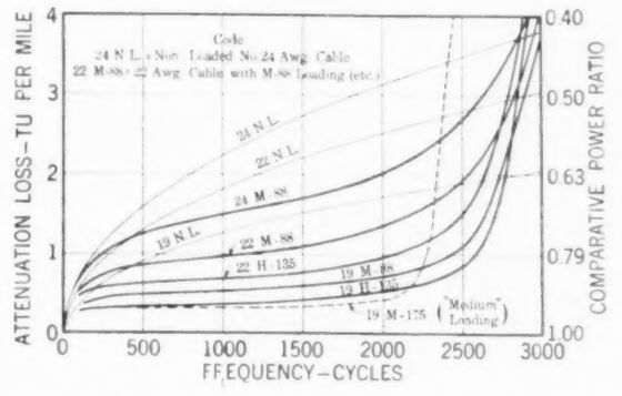
The problem of the plant engineer in laying out trunk cables is to determine for each trunk group the type of facility which will meet the established transmission standards with the lowest cost. The permissible loss in a given length of trunk in a particular area depends on the type of service involved; for instance, a larger loss is allowable in a direct interoffice trunk than in other types of trunks forming part of a toll connection.
The allowable loss for a given length and type of trunk varies widely among different metropolitan areas, due to local conditions. These limits are established by means of "loop-and-trunk" studies which determine for a particular area the most economical allocation of the permissible over-all loss between the subscriber loops and the interoffice trunks. On account of the wide range of local conditions the fields of service of the different types of loaded and non-loaded trunks cannot be sharply defined. An indication of the service uses is given in the upper part of Fig. 16, which illustrates the possible applications of the new standard types of facilities for direct interoffice trunk service, assuming maximum allowable losses of 11 and 15 TU, respectively. The diagram shows, for instance, that M-88 p. 274 loading on No. 22-A.w.g. cable is the preferred construction for trunks from 7.5 to 11.5 miles long, when working to an 11-TU limit. The lower part of Fig. 16 indicates on a cumulative-percentage basis the distribution of direct interoffice trunk lengths in the Bell System.
In the design of the exchange area trunk plant, it is, of course, necessary to consider the signaling characteristics of the facilities and associated equipment, as well as the transmission characteristics. After a certain length is reached in a given type of facility, it may become necessary to use relatively expensive signaling equipment for working longer distances. In some cases of this kind, the total facility cost may be reduced by using a more expensive grade of circuit which will allow less expensive signaling equipment.
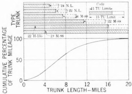
Field of use of different types of loaded and non-loaded facilities, working to 11 to 15 TU limits on attenuation loss. Curve in lower part of diagram shows distribution of trunks with respect to trunk length
In the application of the new standard loading systems, the same standards of over-all attenuation loss are adhered to, as in the older loading systems. In consequence, there is an appreciable improvement in the intelligibility of transmission, due to the ability of the new loading systems to transmit efficiently a range of high frequency voice over-tones which are suppressed by the old standard 2,300-cycle cut-off.
Along with this improvement in service, the new loading systems substantially reduce the plant cost; partly due to the economies which result from the extension of the transmission range of the new types of fine wire cables, and partly because of the use of materially less expensive types of loading coils.
Loading Coils and Cases. As previously noted, the first important change in the coils used for exchange area loading from the early 95-permeability wire core type was the substitution of compressed powdered iron in place of wire for the cores. Initially, only coils having powdered iron cores with a permeability of 60 were designed, as this value corresponds to the effective value of the cores displaced. More recently, in order to better fit in with the requirements of the new cut-off frequency standard, coils using 35-permeability powdered iron cores have been developed. In Table XVII are listed data for the coils now used in exchange area loading.
TABLE XVII
Coils for Loading Exchange Area Cables
| Coil Code No. | Inductance (Henrys) | Core Permeability | Resistance-Ohms: D-C. | 1000 Cycles | Over-all Dimensions Inches: Diameter | Height |
|---|---|---|---|---|---|---|
| 602 | 0.088 | 35 | 8.9 | 10.5 | 3.6 | 1.3 |
| 603 | 0.135 | 35 | 12.8 | 14.1 | 3.6 | 1.3 |
| 574 | 0.175 | 60 | 4.6 | 10.6 | 4.5 | 2.1 |
Effective resistance values are for a line current of 0.001 ampere.
The standardization of the small size Nos. 602 and 603 loading coils has made it possible to design containing cases and assembly methods which permit much larger numbers of coils to be enclosed in cases conforming to the dimensional limitations set by existing vault conditions. A series of cases having capacities up to 300 coils has now been developed. The use of these large potting complements will be of considerable value in reducing the space congestion encountered in the "downtown" sections of the larger metropolitan areas.
In the 300-coil case, a total of 1,200 soldered joints are required to connect the coil terminals to the stub cable conductors. It was accordingly very important that the assembly method should involve a minimum liability to open circuits, crosses, or grounds. To accomplish this, a method was devised whereby the various spindles of coils were assembled to a skeleton frame to which the cable stub containing the 600 terminal pairs is also attached. All splices to the outgoing conductors are made immediately adjacent to the individual p. 276 coil terminals, after which the skeleton unit consisting of the coils and stub cable with case cover attached, is picked up with suitable tackle, and the coil unit inserted in the case. Fig. 17 illustrates this stage of the assembly. The case is subsequently filled with moisture-proof compound and sealed in the usual manner.
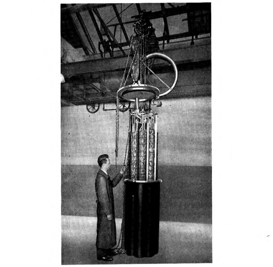
Lowering loading coils into case after coil spindles have been mounted on frame and coil terminals spliced to stub cable conductors
Installation Features. In general, the exchange area cables on which loading is required are run in underground ducts and consequently the great bulk of the exchange area loading is installed in underground vaults. Fig. 18 shows a typical loading installation in a "double-deck" vault in New York City. The loading coil cases p. 277
are placed in the lower part of the vault permitting the coil terminal stub cables to be brought up vertically behind the horizontal cable runs and spliced to the trunk cables in such a way as to minimize the difficulties of future work on the cables passing through the vault. The trunk cables enter the vault through ducts which may be seen at the top of the picture, and are supported on racks mounted on the upper side walls of the vault.
At present, a total of eight loading coil cases is installed in the vault illustrated in Fig. 17. Only five of these, however, appear in the picture. The cases now in place contain a total of 645 loading coils. The vault has space for six additional large cases, on which basis it is estimated that this vault will ultimately contain about 2,400 coils. Some of the largest vaults are capable of accommodating a total of 30 large cases containing a total of 9,000 coils.
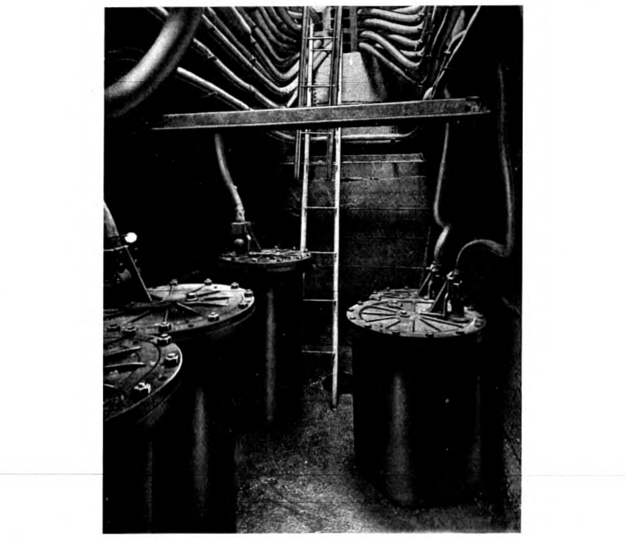
Fig. 18—Underground cable loading coil installation in Metropolitan area. Double-deck vault having ultimate capacity of 14 large coil cases p. 278
VII. Loading for Submarine Cables
Coil Loading. The special problem of applying coil loading to submarine cables is a mechanical one, rather than one concerning the principles of loading. The situation in the United States is such that only a few coil loaded submarine cables have been required; this, of course, does not refer to the considerable number of instances where the submarine cables are so short that ordinary types of coils installed at the terminals satisfy the transmission requirements.
To date there have been installed in the United States a total of five cables having submarine coil loading; details of which are given in Table XVIII.
TABLE XVIII
Coil Loaded Submarine Cables
| Location | Year of Installation | Length of Cable Miles | No. of Load Points | Number of Loaded Ccts. | Spacing of Coils-Miles | Coil Inductance Henrys |
|---|---|---|---|---|---|---|
| Chesapeake Bay No. 1 | 1910 | 4.5 | 2 | 17 pr. 13 A.w.g. | 1.97 | 0.117 |
| Chesapeake Bay No. 2 | 1916 | 4.0 | 1 | 12 qd. 13 A.w.g. | 2.0 | 0.067-S 0.042-P. |
| Tarrytown-Nyack | 1916 | 2.7 | 2 | 37 qd. 16 A.w.g. | 0.89 | 0.250-S 0.155-P |
| Raritan Bay No. 1 | 1917 | 5.3 | 5 | 37 qd. 16 A.w.g. | 0.91 | 0.250-S 0.155-P |
| Raritan Bay No. 2 | 1918 | 5.3 | 5 | 37 qd. 16 A.w.g. | 0.89 | 0.250-S 0.155-P |
The Raritan Bay cables each have 37 quads loaded at five points, 111 coils at each point, constituting the largest installation of submarine coil loading in the world. The depth of water in which these cables are installed is about 35 feet.
In each of the above instances, dry core paper cables were used. The design of the coil was made to fit the special designs required for the submarine loading pots. The case design was such as to furnish complete protection of the coils against moisture penetration and adequate mechanical strength for taking up the tension in the cable. In installing the cables, the procedure was to splice the loading coil cases into the cable while the cable was coiled on a barge, and then lay the cable and coils as a continuous operation. The service record of these p. 279 loaded submarine cables is excellent, thus demonstrating a satisfactory solution of the many difficult mechanical problems involved.
Continuous Loading. Another form of submarine cable loading, first put into practise by the Danish engineer, C. E. Krarup,30 is to wind an iron wire or tape spirally around the copper conductor. This gives a continuous loading which has found important applications in the case of telephone and telegraph cables laid in deep water. So far as land cables are concerned, it has been found that continuous loading is uneconomical in comparison with coil loading. The only instances of continuous loading in the plant of the Bell System are the Florida-Cuba cables,31 connecting Key West and Havana, which are the longest and most deeply submerged cables in use for telephonic communication in the world.
VIII. Extent of Commercial Application
The following data will assist in visualizing the practical importance of the developments which have been described in this paper.
In 1911, when Mr. Gherardi addressed this Institute on the subject of loading practise in this country, there were about 125,000 loading coils in service which loaded about 85,000 miles of open wire circuits and 170,000 miles of cable circuits. Although precise figures are not yet available regarding the number of loading coils in service in the Bell System as of January 1, 1926, conservative estimates set this total at about 1,250,000 coils. These coils load about 1,600,000 miles of cable circuits and 250,000 miles of open wire. In round numbers, 500,000 coils are installed on non-quadded local area trunk cables and 700,000 in toll and toll entrance cables (the bulk of these being quadded cables). Nearly two-thirds of the total number of coils have compressed iron powder cores, all of these being installed on cable circuits. About 4500 coils having wooden cores are installed on carrier loaded entrance cables. The remainder have iron wire cores, approximately 60,000 being of the so-called "air-gap" types.
Prior to the development of satisfactory types of telephone repeaters, the principal use of loading coils was in exchange area trunk cables in large metropolitan areas such as New York, Chicago, Philadelphia, and Boston. The successful application of telephone repeaters to loaded small gage cables has greatly increased the use of loading in the telephone plant. As illustrating this trend, approximately 150,000 toll p. 280 cable coils were manufactured for the Bell System in 1925, and approximately 100,000 exchange area cable coils. Recent estimates of the loading coil requirements for the next five years indicate an annual demand at a rate which would double the total number of loading coils in service about 1930.
As regards the field of application for cable loading in terms of cable lengths, the entrance and intermediate cables represent the minimum lengths; for instance, pieces as short as 500 feet when present in carrier telephone systems may require loading. In the local exchange areas, toll switching trunks as short as two miles may require loading. On the other hand, as illustrating the longest circuit now entirely in cable, a connection between Boston and Milwaukee—via New York, Pittsburgh, Cleveland, and Chicago—typifies the possibilities in the existing repeatered loaded cable plant. The over-all length of such a circuit is approximately 1200 miles. There is no technical obstacle to the use of repeatered loaded cables for distances several times as great; i.e., in the present state of the art, this is primarily a question of economics rather than of development.
IX. Conclusion
It will be appreciated from the foregoing account that the invention of coil loading was the beginning of an era of intensive development which has been marked by enormous advances in the design of telephone transmission lines, and that there has been no slackening of the inventional or development activity devoted to this subject. It is significant that at present more engineers and physicists in the departments represented by the authors are engaged on loading development problems than at any previous time.
In this account of the progress of the loading art during the past quarter century, the authors have endeavored to point out the relation of the loading developments to other phases of telephone development such as cables, repeaters, telegraph working, and carrier telephone and telegraph systems. In the space that is available, it would be impracticable to assign full credit to the many individuals who have been engaged in the development work on loading and the related problems. The final accomplishments should be regarded as the result of well coordinated efforts along many lines.
In conclusion, it may be of interest to note what the development and use of loading has meant to the telephone using public from an economic standpoint. Leaving out of consideration altogether loading on long toll cables—where the interdependence of repeaters and loading p. 281 is such that it is impracticable to assign to each its share of the savings—and taking into consideration only the loading of interoffice trunks and toll open wire circuits, it has been estimated that the larger wires which would have been required to give the present grade of transmission if loading had not been available, taken together with the heavier pole lines and additional underground ducts, would have entailed an additional investment in Bell System telephone plant of over $100,000,000.
Bibliography
In addition to the references already cited, the following will be of interest:
Vaschy, Annales Telegraphiques, 1886, p. 321.
Heaviside, Electrician (London) June 3, 1887.
Vaschy, La Lumiere Electrique, 1889, 31, 83.
Heaviside, "Electromagnetic Theory," Vol. 1, 1893, p. 441.
S. P. Thompson, "Ocean Telephony," Proceedings Electrical Congress, World's Fair at Chicago, 1893.
M. I. Pupin, "Propagation of Long Electrical Waves," Trans. A. I. E. E., Vol. 16, 1899, 93.
W. A. J. O'Meara, "Submarine Cables for Long Distance Telephone Circuits," Journal I. E. E. London, April, 1910.
F. Bresig, Theoretische Telegraphie, 1910.
J. A. Fleming, "Propagation of Electric Currents," Van Nostrand Company, 1911.
A. E. Kennelly, "The Application of Hyperbolic Functions to Electrical Engineering Problems," University (London) Press, 1912.
A. Ebeling, ETZ., 1914, p. 695 and p. 728.
K. W. Wagner, Archiv für Electrotechnik, Vol. 3, 1915, p. 315.
J. G. Hill, "Telephonic Transmission," London, Longmans, 1920.
K. W. Wagner, and K. Küffmüller, Archiv für Electrotechnik, Vol. 9, 1921, p. 461.
Sir Wm. Noble, "Long Distance Telephone System of the United Kingdom," Journal I. E. E., Vol. 59, p. 389, 1921.
Das Fernsprechen Im Weitverkehr—Reichspostministerium, Berlin, 1923.
R. S. Hoyt, Impedance of Smooth Lines and Design of Simulating Networks, Bell System Technical Journal, April, 1923.
L. D. Cahen, Le Progres et l'Etat Actuel de la Technique des Liques Pupinisees—Bulletin de la Société francaise des Electriciens Aug.-Oct. 1924 (4 Serie), 4:755.
K. S. Johnson, Transmission Circuits for Telephonic Communication, Van Nostrand Co., 1925.
Notes
-
Presented at the Midwinter Convention of the A. I. E. E., New York, N. Y., February 9, 1926. ↩
-
"Commercial Loading of Telephone Circuits in the Bell System," B. Gherardi, Trans. A. I. E. E., Vol. 30, 1911, p. 1743. ↩
-
This section on Theory contains a small amount of discussion not included in the paper as presented. ↩
-
"Wave Transmission over Non-Uniform Cables and Long Distance Air Lines," M. I. Pupin, Trans. A. I. E. E., Vol. 17, 1900, p. 445. Refer also to Pupin, U. S. Patents Nos. 652, 230 and 652, 231, June 19, 1900. ↩
-
"On Loaded Lines in Telephone Transmission," G. A. Campbell, Philosophical Magazine, March, 1903. ↩
-
"The Transmission Unit and Telephone Transmission Reference Systems," W. H. Martin, Trans. A. I. E. E., Vol. 43, 1924, p. 797; Bell System Technical Journal, July, 1924. ↩
-
U.S. Patents No. 980,021 "Loaded Phantom Circuit," G.A.Campbell and T. Shaw. No. 981,015 "Phantomed Loaded Circuit," T. Shaw. ↩
-
"Commercial Loading of Telephone Cable," W. Fondiller, Electrical Communication, July 1925. ↩
-
"Telephone Repeaters," B. Gherardi and F. B. Jewett, Trans. A. I. E. E., Vol. 38, 1919, p. 1287. ↩
-
"Telephone Transmission over Long Cable Circuits," A.B.Clark, Trans. A. I. E. E., Vol. 42, 1923, p. 86; Bell System Technical Journal, Jan., 1923. ↩
-
R. S. Hoyt "Impedance of Loaded Lines and Design of Simulating and Compensating Networks," Bell System Technical Journal, July 1924. ↩
-
U. S. Patents Nos. 1,227,113, and 1,227,114—G. A. Campbell. ↩
-
U. S. Patent No. 1,219,760—John Mills and R. S. Hoyt. ↩
-
U. S. Patents Nos. 1,289,941 and 1,433,305—Shaw and Fondiller. ↩
-
U. S. Patents No. 1,274,952, B. Speed; 1,286,965, G. W. Elmen; 1,292,206, J. C. Woodruff. ↩
-
"Magnetic Properties of Compressed Powdered Iron," B. Speed and G. W. Elmen, Trans. A. I. E. E., Vol. 40, 1921, p. 1321. ↩
-
Minutes of Second Conference of Permanent Commission, Le Comité Consultatif Internationale de Communications Telephonique a Grande Distance, page 55—p. 119, English Version. ↩
-
"Echo Suppressors for Long Telephone Circuits," A. B. Clark and R. C. Mathes, Jour. A. I. E. E., p. 618, June, 1925. ↩
-
Clark, Loc. Cit. ↩
-
"Theory of the Transient Oscillations of Electrical Networks and Transmission Systems," J. R. Carson, Trans. A. I. E. E., Vol. 38, 1919, p. 345. ↩
-
Gherardi—Jewett, Loc. cit. ↩
-
"Philadelphia-Pittsburgh Section of New York-Chicago Cable," J. J. Pilliod, Trans. A. I. E. E., Vol. 41, 1922, p. 446; Bell System Technical Journal, Jan., 1922. ↩
-
"Telephone Transmission over Long Distances," H. S. Osborne, Trans. A. I. E. E. Vol. 42, 1923, p. 984. ↩
-
"Carrier Current Telephony and Telegraphy," E. H. Colpitts and O. B. Blackwell, Trans. A. I. E. E., Vol. 40, 1921, p. 205. ↩
-
U. S. Patents Nos. 1,501,959, Martin and Shaw; 1,501,926, Shaw. ↩
-
U. S. Patent No. 1,394,062—O. B. Blackwell. ↩
-
"Hysteresis Effects with Varying Superposed Magnetizing Forces," W. Fondiller and W. H. Martin, Trans. A. I. E. E., Vol. 40, 1921, p. 443. ↩
-
"Metallic Polar-Duplex Telegraph System for Cables," Messrs. Bell, Shanck and Branson, Trans. A. I. E. E., 44:337, 1925. ↩
-
"Voice-Frequency Carrier Telegraph Systems for Cables," Messrs. Hamilton, Nyquist, Long and Phelps, Trans. A. I. E. E., Vol. 44, 1925, p. 327. ↩
-
C. E. Krarup, Submarine Telephone Cables with Increased Self-Induction, ETZ., 23:344, April 17, 1902. ↩
-
W. H. Martin, G. A. Anderegg, B. W. Kendall, "Key West-Havana Submarine Telephone Cable System," Trans. A. I. E. E., Vol. 41, 1922, p. 184. ↩