Carrier-Current Communication on Submarine Cables: Los Angeles-Catalina Island Telephone Circuits
Cite this paper
H. W. Hitchcock, "Carrier-Current Communication on Submarine Cables: Los Angeles-Catalina Island Telephone Circuits," Bell System Technical Journal, vol. 5, no. 4, October 1926, pp. 636–651.
Full text
Carrier-Current Communication on Submarine Cables
Los Angeles-Catalina Island Telephone Circuits1
By H. W. HITCHCOCK
Synopsis: Seven telephone channels and one telegraph channel on one single-conductor deep-sea cable have been made possible by the employment of carrier current on one of the two submarine cables across Catalina channel. This is the only application of carrier telephony to deep-sea cables and the system is one of the shortest carrier systems (26 mi.) in commercial operation; it provides more separate carrier channels (six) than has been previously attempted; and it differs in other important respects from other systems. This paper describes this carrier-current system.
IN the commercial application of new developments in the electrical communication art, there are a few places which repeatedly call attention to themselves. Notable among these is Catalina Island, for it is probable that in providing telephone service across the short expanse of water which separates Catalina from the mainland, more novel improvements have been employed than at almost any other point.
The first commercial telephone communication with Catalina Island was established in 1920 when a radio system was placed in operation between Avalon and the mainland, the circuit being extended by wire to Los Angeles. This circuit was in use for several years and featured in a number of transcontinental demonstrations, including the one which was held at the opening of the service to Havana over the Key West-Havana cables.
The system is of considerable interest as it represents the only instance in which radio has been used, in this country at least, to form a portion of a toll telephone system for the general use of the public. That it was reasonably successful is demonstrated by the fact that on some days as many as 183 commercial telephone messages and a large number of telegrams were handled over it. The system also proved to be one of the first popular broadcasting stations and many letters were received from radio fans, often several hundred miles away, telling of some of the amusing conversations which were overheard.
In 1923 the radio was replaced by two single-conductor submarine cables. By that time the demands for service were too great to be met by a single circuit, while the growing interest in radio broadcasting, as well as the increasing interference from ship transmitters, p. 637 rendered its continued operation very difficult and unsatisfactory. The submarine cables were of the single-conductor, deep-sea type, each providing a single-wire circuit. They are of interest for a number of reasons, chiefly, perhaps, because they represent one of the few instances of deep-sea cable manufacture in this country. From the cable hut at San Pedro, the circuit is extended to the office by means of a special lead-covered cable containing four individually shielded No. 13 B & S gauge pairs for the telephone circuits and four 19-gauge pairs for the telegraph circuits and other miscellaneous uses. Between the San Pedro office and Los Angeles, the circuit was composed of a No. 19 B & S gauge cable phantom. At San Pedro a through-line repeater was inserted in order to secure the desired over-all equivalent between Avalon and Los Angeles.2
Although the two circuits provided by the cables represented a great improvement over the previous condition as regards the quality of the service rendered and the number of messages which could be handled, it was realized that they would soon prove inadequate to handle the heavy summer business, for which eight or ten circuits would be required in a relatively short time. To provide for such a large increase by the laying of additional cables was deemed impracticable, as the cost would be excessive. Furthermore, in water of this depth—3,000 feet—it is important that cables be laid at least a mile or two apart, so that in the event that trouble develops on one, it can be repaired without disturbing any of the others. For a total distance as short as the width of the Catalina channel—23 nautical miles—such a separation between adjacent cables could not be maintained without materially increasing the length of the outer ones with a corresponding increase in their cost and in their transmission equivalents. In view of these facts, it was decided to secure as many more circuits as possible by operating carrier systems over the two cables already in use. This project was actively promoted with the result that on May 15, 1926, six carrier telephone circuits were placed in operation.
The use of carrier in the past few years has increased so rapidly that the mere addition of a new system is, in itself, of hardly more than passing interest. In this instance, however, there are a number of factors which render the project of particular interest. It is one of the shortest carrier systems—26 miles—in commercial operation. It is the only application of carrier telephone to deep-sea cables; the system provides p. 638 more separate channels (six) than has ever before been attempted, while the particular arrangement employed is different in many other important respects from anything which has been used in the past.
In order to better appreciate the reasons for adopting the system finally agreed upon, it may be of interest to review briefly the essential characteristics of carrier systems and the different types which are available.3
Carrier systems may be divided into two general classes, namely, balanced or grouped, depending upon the manner in which the currents in the two directions are prevented from interfering with each other at the terminals. In the balanced system this separation is accomplished by means of a three-winding transformer or hybrid coil together with a balancing artificial line such as is used with a voice-frequency repeater. In the grouped system, different carrier frequencies are used for transmission in the two directions and their separation at the terminals is effected by means of suitable band-pass filters. These two systems are shown diagrammatically in Fig. 1. The balanced system has the advantage that for each channel p. 639 the same carrier frequency may be used for transmission in both directions so that there may be as many channels as there are separate carrier frequencies. On the other hand, the wire circuit must be very uniform throughout so that the impedance will be very regular over the entire carrier-frequency range, and may be simulated by an artificial line. The line must also be very stable so that the impedance balance, once having been secured, will not be disturbed. Furthermore, as transmission with the same carrier takes place in the two directions, the effect of the cross-talk between systems of the same type is very severe, so that it is usually impracticable to operate two of these over wires which are in close proximity for any considerable distance. The grouped system has the advantage that a balancing line is not required and hence small circuit irregularities are relatively unimportant. Furthermore, the effect of cross-talk is much less severe, so that a number of systems may often be operated over adjacent circuits. One disadvantage is that two carrier frequencies are required for each channel so that fewer circuits can be secured with one system.
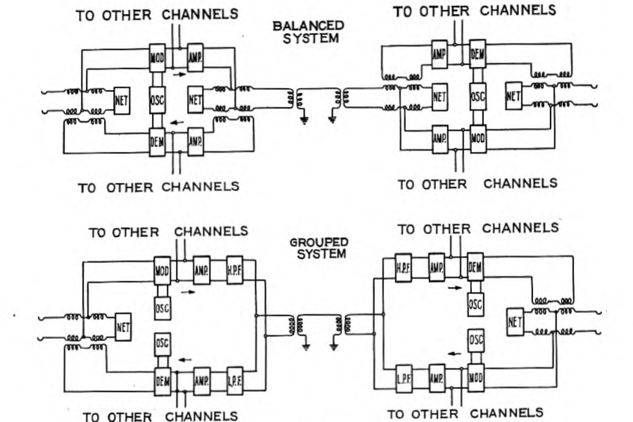
Carrier systems may also be divided into two classes depending upon the manner in which the carrier current is provided at the receiving end. In the carrier transmission system, the carrier current is supplied by the oscillator at the sending end and is transmitted over the circuit along with one or both of the side bands. In the carrier suppression system, the carrier current itself is not transmitted but is introduced into the receiving equipment from a local source. This latter system is proving to be superior for general carrier purposes because of the advantages which accrue from relieving the line and apparatus from the load of the carrier current.
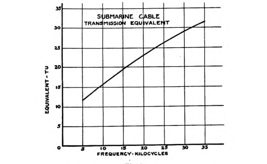
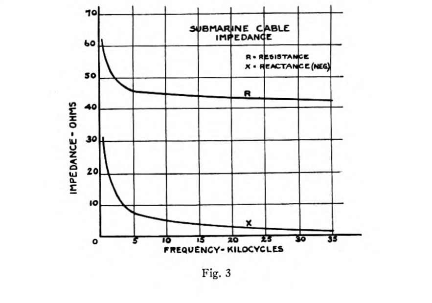
Turning now to the electrical characteristics of the cables, we find that each one provides a circuit having a transmission equivalent which increases throughout the carrier range but is moderate in magnitude. The impedance, as is to be expected with a uniform, non-loaded cable, is very smooth, and since there is no opportunity for any change in the cable constants, the impedance has practically no variation. The transmission equivalent and the impedance of one of the cables are shown in Figs. 2 and 3, respectively. The cross-talk between the cables is small enough to be entirely negligible, regardless of the type of carrier systems employed.
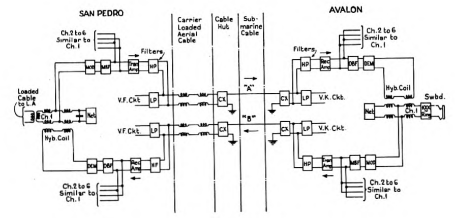
In view of all the conditions outlined, a balanced system of the carrier suppression type was decided upon. Such a system provides the maximum number of channels per cable, while the usual difficulties of impedance balance and inter-system cross-talk are largely p. 640 absent due to the unusual characteristics of the cables. The adoption of such a system also made possible the employment of standard units of equipment of the most recent design. The general nature of the system and the arrangement of the component parts is shown diagrammatically in Fig. 4. Fig. 5 is a simplified circuit diagram p. 641 showing the filters for separating the various circuits at the terminals, together with the balancing arrangement. In Fig. 6 are shown the essential parts of one channel together with the amplifiers and the hybrid coil which are common to all the channels. For convenience, some of the battery and auxiliary circuits have been omitted in the figure.
At the time the system was under development, it was uncertain that balanced operation of all channels over a single cable would be practicable, so that an alternative arrangement involving substan- tially four-wire operation over the two cables was provided for. With this arrangement, which is shown diagrammatically in Fig. 7, all transmission in one direction takes place over one cable, while transmission in the opposite direction is effected over the second cable. No balancing equipment or hybrid coils are employed. Such an arrangement would increase the system stability, if such were required, but would limit the total carrier capacity of the two cables to six channels. In the event of the failure of one cable, operation with such a system would be impossible, and it would be necessary, at that time, to revert to the two-wire arrangement as described above, with a possible reduction in the over-all gain or a reduction in the number of operating channels.
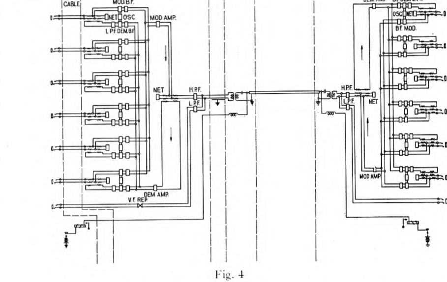
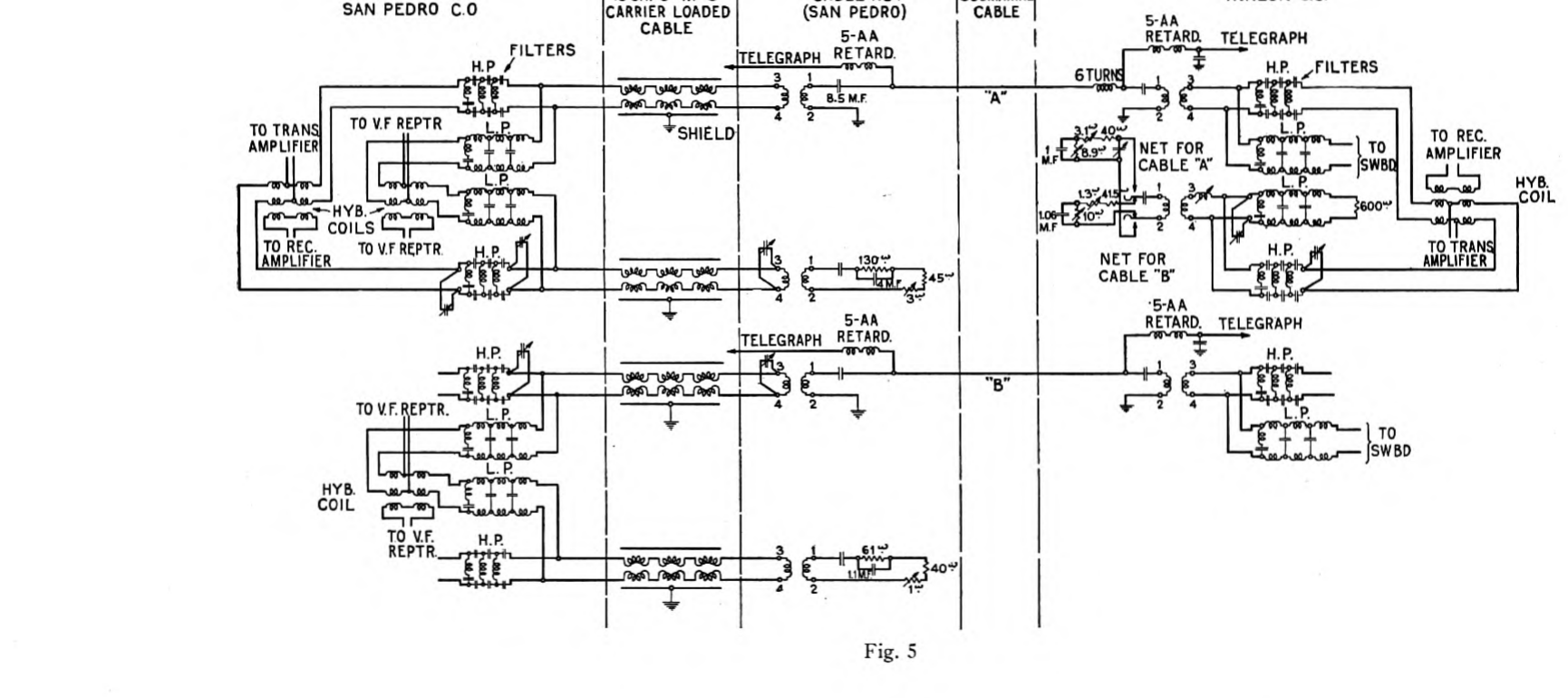
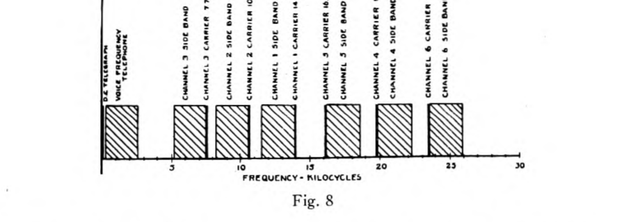
As may be seen from Fig. 4, a carrier-equipped cable provides a d-c. telegraph circuit, and one voice-frequency and six carrier-frequency telephone channels. The separation of the various channels is effected by means of electrical filters. Fig. 8 shows the band of frequencies employed for each channel. For the d-c. telegraph this separation is effected at the terminals of the cable as is shown in Fig. 5. The telegraph circuit requires a continuous d-c. path, whereas the telephone channels require the insertion of an inequality ratio insulating transformer at the ends of the cable in order to properly join the 43-ohm grounded cable circuit with the 600-ohm metallic p. 644 circuit formed by the office equipment and intermediate cable. As this transformer must pass both the voice and carrier channels, it has been designed so as to have a high efficiency for all frequencies between 250 and 30,000 cycles. Separation of the voice-frequency circuit from the carrier system is performed by means of the usual high and low pass filters which are located at the central offices. These filters both have a cut-off frequency of 3,000 cycles, the low pass transmitting all frequencies below this value and the high pass transmitting all above it. In the carrier system the transmitting and receiving currents are separated from each other by a hybrid coil and balancing network. Between the output of the six modulators and the common transmitting amplifier, individual band-pass filters are located. Each one of these filters is designed to transmit one of the side bands produced by the modulator associated with it and to suppress all other frequencies. The six receiving currents are separated in a similar manner. Each filter allows current of the proper frequency to pass to the corresponding demodulator and excludes all others. Each demodulator is also provided with a low pass filter which allows the passage of the resulting voice-frequency current but excludes all incidental higher frequencies which might be present and render the circuit noisy. The input of each modulator and the output of the corresponding demodulator are finally joined by means of a voice-frequency hybrid coil and extended to the circuit terminal as a two-wire circuit. At the San Pedro end, each two-wire circuit is extended to Los Angeles over a loaded cable circuit. Phantoms are employed for this purpose as they have a higher cut-off frequency than have the side circuits, with a correspondingly better quality.
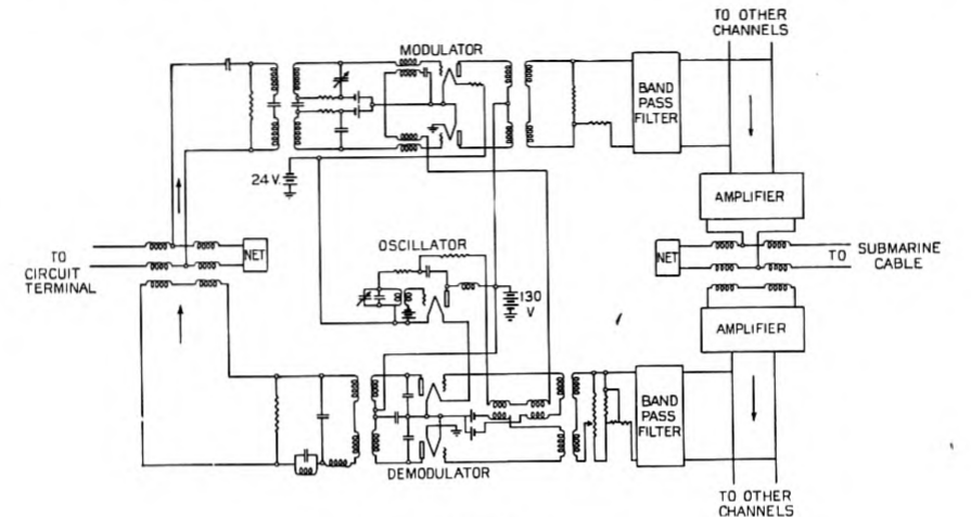
Concerning the carrier system itself, the two ends are practically identical while the general equipment arrangement for an individual p. 645 channel is the same in all cases except for the frequency of the band-pass filter. For this reason, a consideration of one channel is sufficient. Each channel is composed of a voice-frequency hybrid coil, a modulator with its band-pass filter, an oscillator, and a demodulator, together with its associated filters. In addition, there is, at each end, a carrier hybrid coil together with transmitting and receiving amplifiers which are common to all channels. The arrangement of this equipment is shown schematically in Fig. 6, as previously indicated.
The modulator, the input of which is connected to the center taps of the hybrid coil line windings, utilizes of two vacuum tubes arranged for push-pull operation. The carrier current which is supplied by the oscillator is applied to the two grids by means of a transformer. Such a circuit generates the two side bands but suppresses the carrier. In order that this suppression may be as complete as possible, the small condenser associated with the grid of one of the tubes is made variable and is adjusted until the carrier current in the modulator output is reduced to a minimum. The band-pass filter transmits one of the side bands and suppresses the other, as well as all miscellaneous resultant currents of a higher order which are produced by the modulator. It also prevents the output currents of the other channels from entering the modulator circuit as this would cause a reduction in their efficiency and give rise to undesirable frequencies.
The demodulator is very similar to the modulator. The tube arrangement is substantially the same and carrier current is supplied from the one oscillator. In the demodulator a complete suppression of the carrier is unnecessary as this is accomplished by the low pass output filter. For this reason, the small balancing grid condensers are omitted. In order to adjust the over-all gain of the channel, the demodulator is provided with an adjustable potentiometer graduated in two transmission unit steps, and in addition, fixed pads are provided for making further gain adjustments. The output of the demodulator is connected to the series winding of the voice-frequency hybrid coil.
The oscillator which supplies the carrier current to the modulator and demodulator is of the usual type. The tuning condenser includes a small variable unit for making small adjustments in frequency. Separate oscillators are used at the two ends for each channel, and as these are in no way connected together, it is occasionally necessary to make slight adjustments in order to keep the frequencies at the two ends substantially equal. The oscillators are very stable, however, and such adjustments are seldom required.
The individual channel filters are all of the band-pass type as previously indicated and have a free transmission range of approximately 2,500 cycles. Outside this free range they have a high impedance so as not to act as a shunt for the other channels. They are all of substantially the same construction, although the constants of the component parts necessarily vary as the filters for the different channels transmit different frequencies.
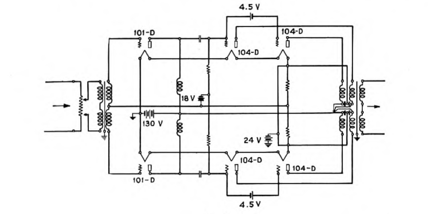
The transmitting and receiving amplifiers, which are practically identical, are shown schematically in Fig. 9. They consist of two push-pull stages connected in tandem. Each half of the second or output stage consists of two parallel tubes of high output capacity. In this way a comparatively high gain and a large energy output may be secured without overloading. This is very important as these amplifiers are common to all six channels and any tendency to overload would produce objectionable distortion and inter-channel modulation. In order to adjust the over-all gain for the entire system, each amplifier is provided with an input potentiometer.
As has been previously indicated, the transmitting and receiving circuits are joined to the cable by means of hybrid coils. Probably the most difficult problem encountered in the installation of this system was the securing of an adequate balance. The difficulty of doing this may be better appreciated when it is realized that this balance must cover all frequencies from 3,000 to 30,000 cycles, and must have a value of from 30 to 45 T. U., the higher value which represents an impedance unbalance of approximately one per cent. being required at the upper frequency. In order to secure such a p. 647 balance, every part of the line circuit was matched by a similar part in the network circuit. All filters and transformers on the line side of the hybrid coil were duplicated in the network, and on the San Pedro side a 13-gauge carrier-loaded cable pair was included in the network circuit between the office and the cable hut, and the inequality ratio transformer and basic network simulating the cable were located at the latter point. In addition to providing a balance within the carrier range, it was necessary at the San Pedro end for the network circuit to balance the cable within the voice-frequency range as a through-line repeater is employed on the voice-frequency circuit. Not only was it necessary to duplicate all parts in the line and network circuits but in addition they were carefully selected and paired so that the two parts associated would have, as nearly as possible, the same electrical characteristics. All wire pairs within the office which appeared in the carrier frequency circuits were individually shielded by means of a grounded metallic covering. The 13-gauge carrier-loaded pairs in the cable joining the hut and the office were also individually shielded by means of a lead foil wrapping. This was done in order to preserve the balance and prevent cross-talk with another system which may be placed on the second cable at some future time.
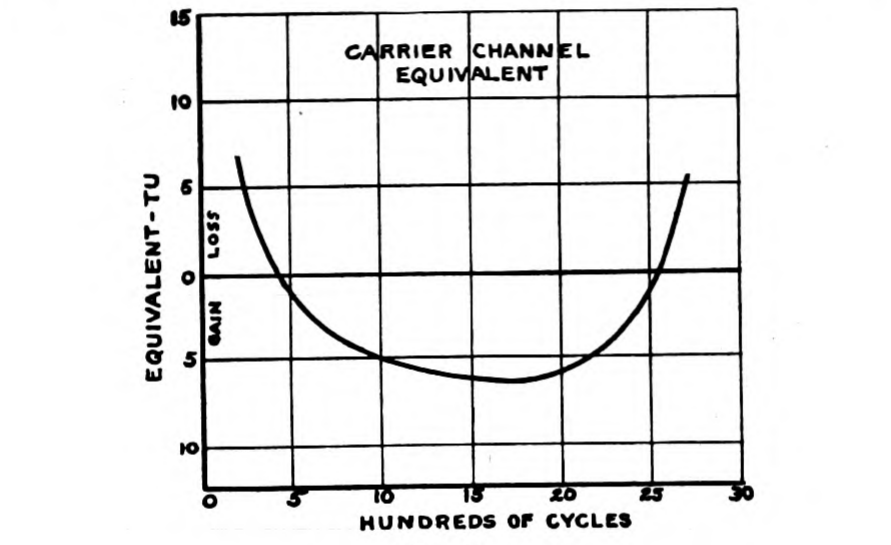
Although extreme care was exercised in making the refinements described, the balance was still lower than was desired so that small p. 648 variable auxiliary impedances were inserted at suitably chosen points in the line and network circuits. By the adjustment of these elements, it was found that the balance could be raised to any desired value for any particular channel, but that in so doing, the balance on some of the others would be impaired. By careful adjustment, however, it was possible to secure a balance for all channels within the range previously mentioned. As the transmission equivalent of the cable increases with the frequency, the over-all channel gains must be increased in the same manner in order that all circuits may have the same over-all equivalent. The networks were therefore arranged so that the higher frequencies would have the better balance, as in that way the margin of balance over gain could be made substantially the same for all channels. Since this margin should not be allowed to fall below a fairly definite minimum if the circuit is to have the p. 649 desired stability, it is evident that the balance which may be secured determines the over-all gain which is possible. In this case the circuit equivalent for all channels between Los Angeles and Avalon was set at five T. U. As the loaded cable between Los Angeles and San Pedro is approximately nine T. U., it may be seen that the carrier system actually introduces a gain and performs the function of a repeater besides increasing the number of circuits. Fig. 10 gives a frequency characteristic of one of the channels which is typical of all of them. Balancing equipment has been provided for both cables as is shown in Fig. 5. With this arrangement, the carrier system may be operated over either cable. The transfer from one cable to the other is so simple that it can be made with practically no traffic interruption.
Signaling over the carrier channels is effected by means of 1,000-cycle ringers which are connected to the circuits at the two terminals. As the ringing current is within the voice range, it is transmitted over the regular carrier channel so that no additional signaling equipment is necessary.
In order to insure satisfactory operation, all necessary testing facilities are included. Meters and keys are provided for measuring the voltages of the plate, grid and filament batteries as well as the plate and filament currents of all tubes. Individual rheostats are inserted in all filament circuits for making any adjustments that may be necessary. Alarms are provided to indicate any abnormal condition which might develop on any tube. Thermocouples and artificial lines have been conveniently arranged for checking the efficiency of all units such as the modulators and demodulators. Jacks are located at suitable points so that any changes which may be necessary can be quickly made.
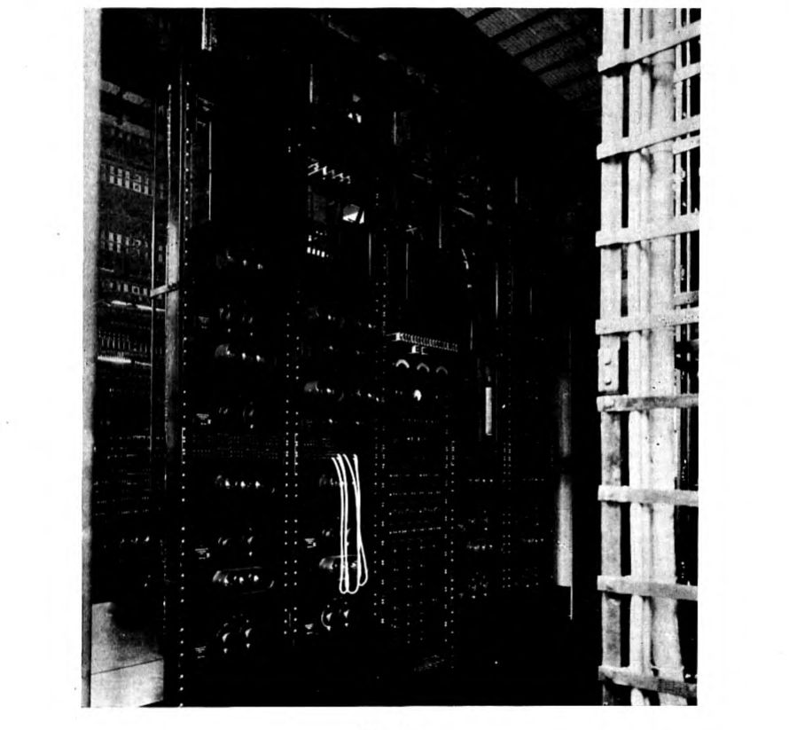
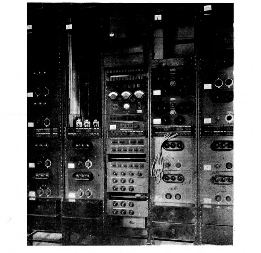
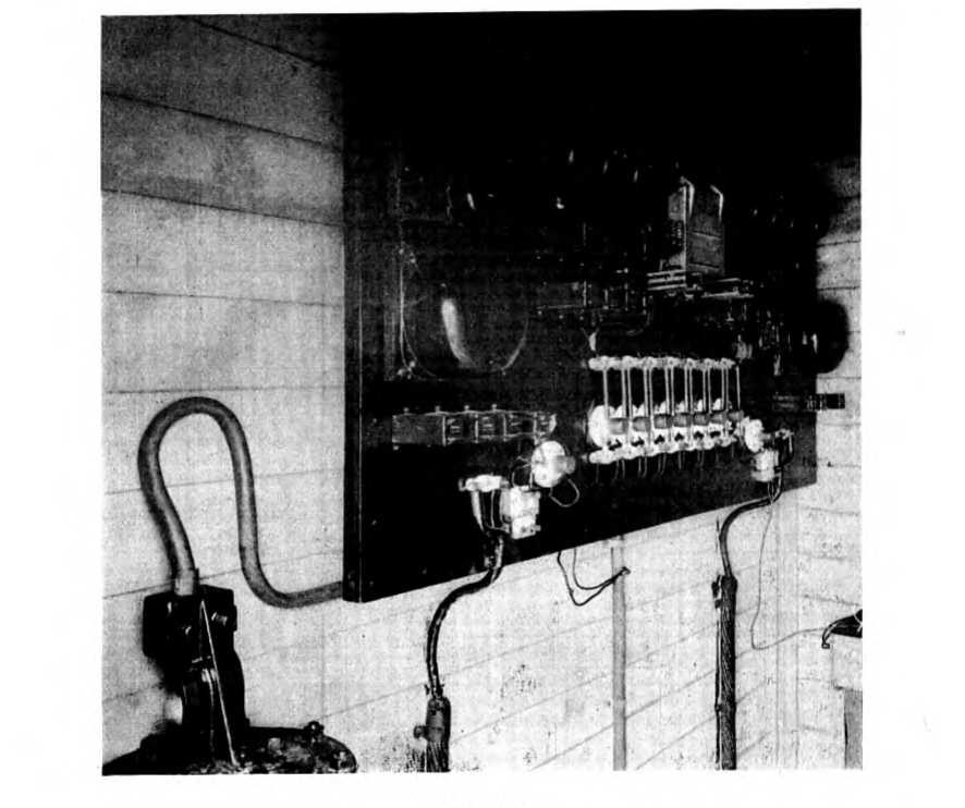
The general appearance of the carrier system may be seen from Figs. 11 and 12 which show the equipment at San Pedro and Avalon respectively. Fig. 13 is an interior view of the San Pedro cable hut showing the cable terminals, together with the insulating transformers, telegraph composite sets, and basis networks. Referring to the central office equipment, the first bay contains the equipment for two complete channels. At the top are the terminal strips for making all connections with the equipment below. On the next two small panels are mounted the hybrid coils and the other miscellaneous apparatus associated with the voice-frequency ends of the two channels. Below these are the modulator and demodulator band filters which are covered with dust proof cases. Next comes the modulator and demodulator panels for one channel. Below the two jack strips is mounted similar equipment for a second channel but arranged in reverse order. In the upper half of the second bay is located a small panel mounting the carrier hybrid coil and associated equipment. Below this appear the transmitting and receiving amplifiers. The lower half of the bay is similar to the lower half of the first one. In the third bay is mounted all the battery supply and testing apparatus. The first two units contain the battery retard coils. Below these are the alarm relays and auxiliary resistances. Next come the meters for measuring the tube currents and voltages, and below these are the thermocouples and artificial lines for making high frequency measurements. Below the jack strip are the keys for opening and closing the individual filament circuits used for measuring the plate and filament currents. Alarm lamps are also associated with each of the filament circuits. The fourth bay is similar to the second except that the upper half is vacant. As may be seen from the photographs, the amplifiers appear on the second bay at San Pedro and on the fourth at Avalon. The fifth bay is an exact duplicate of the first.
The new system has now been in successful operation for the past five months. In the light of its performance thus far, we feel assured, that when more circuits are required a second system of six channels can be added to the second cable, thus providing a total of fourteen telephones and two telegraph circuits over the two single-conductor cables. Such a circuit group, we believe, will meet the traffic requirements for quite a number of years.
Notes
-
Presented at the Pacific Coast Convention of the A. I. E. E., Salt Lake City Utah, Sept. 6–9, 1926. ↩
-
A description of these cables and their laying was given in a paper presented by the writer at the Pacific Coast Convention in 1923 and published in Volume XLII of the Transactions. ↩
-
The general principles of carrier-current telephony are described at considerable length in a paper by Messrs. Colpitts and Blackwell which was published in Volume XL of the Journal of the Institute. ↩
