The Loaded Submarine Telegraph Cable
Cite this paper
O. E. Buckley, "The Loaded Submarine Telegraph Cable," Bell System Technical Journal, vol. 4, no. 3, July 1925, pp. 355–374.
Full text
The Loaded Submarine Telegraph Cable1
By OLIVER E. BUCKLEY
Synopsis: With an increase of traffic carrying capacity of 300% over that of corresponding cables of the previous art, the New York-Azores permalloy-loaded cable marks a revolution in submarine cable practice. This cable represents the first practical application of inductive loading to transoceanic cables. The copper conductor of the cable is surrounded by a thin layer of the new magnetic material, permalloy, which serves to increase its inductance and consequently its ability to transmit a rapid succession of telegraph signals.
This paper explains the part played by loading in the operation of a cable of the new type and discusses some of the problems which were involved in the development leading up to the first commercial installation. Particular attention is given to those features of the transmission problem wherein a practical cable differs from the ideal cable of previous theoretical discussions.
Brief mention is made of means of operating loaded cables and the possible trend of future development.
Permalloy Loading
THE announcement on September 24, 1924, that an operating speed of over 1,500 letters per minute had been obtained with the new 2,300 mile New York-Azores permalloy-loaded cable of the Western Union Telegraph Company, brought to the attention of the public a development which promises to revolutionize the art of submarine cable telegraphy. This announcement was based on the result of the first test of the operation of the new cable. A few weeks later, with an improved adjustment of the terminal apparatus, a speed of over 1,900 letters per minute was obtained. Since this speed represents about four times the traffic capacity of an ordinary cable of the same size and length, it is clear that the permalloy-loaded cable marks a new era in transoceanic communication.
The New York-Azores cable represents the first practical attempt to secure increased speed of a long submarine telegraph cable by inductive loading and it is the large distributed inductance of this cable which is principally responsible for its remarkable performance. This inductance is secured by surrounding the conductor of the cable with a thin layer of permalloy. Fig. 1 shows the construction of the deep sea section of the cable. In appearance it differs from the ordinary type of cable principally in having a permalloy tape 0.005 inch thick and 0.125 inch wide, wrapped in a close helix around the stranded copper conductor.
Permalloy, which has been described by Arnold and Elmen,2 is an alloy consisting principally of nickel and iron, characterized by very p. 356 high permeability at low magnetizing forces. The relative proportion of nickel and iron in permalloy may be varied through a wide range of additional elements as, for example, chromium may be added to secure high resistivity or other desirable properties. On account of its extremely high initial permeability a thin layer of permalloy wrapped around the copper conductor of a cable greatly increases its inductance even for the smallest currents.
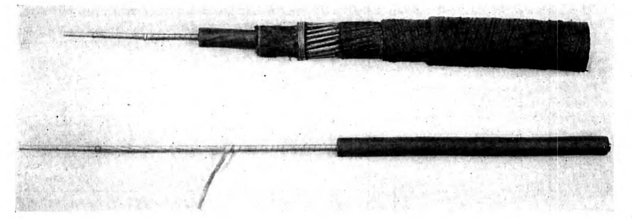
In the case of the New York-Azores cable the permalloy tape is composed of approximately 78½% nickel and 21½% iron and gives the cable an inductance of about 54 millihenries per nautical mile. An approximate value of the initial permeability of the permalloy in that cable may be got by assuming the helical tape replaced by a continuous cylinder of magnetic material of the same thickness.3 This material would have to have a permeability of about 2,300 to give the observed inductance. A better appreciation of the extraordinary properties of the new loading material may be obtained by comparing this permeability with that which has previously been obtained with iron as the loading material. The Key West-Havana telephone cables are loaded with 0.008 inch diameter soft iron wire. The permeability of this wire, which was the best which could be obtained commercially when that cable was made, is only about 115, p. 357 or approximately one-twentieth that of the permalloy tape of the New York-Azores cable.
Problems Encountered
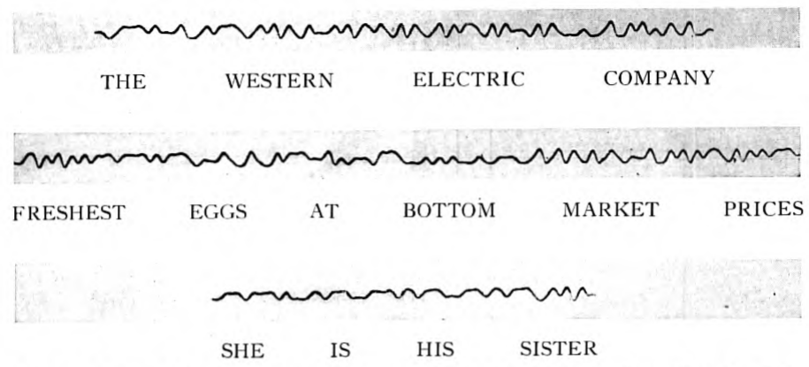
The proposal to use permalloy loading to increase the speed of long telegraph cables was one outcome of an investigation undertaken by the author soon after the war to determine whether some of the new methods and materials developed primarily for telephony might not find important application to submarine telegraphy. In the subsequent development of the permalloy loaded cable a large number of new problems, both theoretical and practical, had to be solved before the manufacture of a cable for a commercial project could be undertaken with reasonable assurance of success. The problems encountered were of three principal kinds. First was that of the transmission of signals over a cable having the characteristics of the trial conductors made in the laboratory. Although the theory of transmission over a loaded cable had been previously treated by others, the problem considered had been that of an ideal loaded cable with simple assumptions as to its electrical constants and without regard to the practical limitations of a real cable. The second class of problems had to do with the practical aspects of design, manufacture and installation. In this connection an extensive series of experiments was conducted to determine the means required to secure at the ocean bottom the characteristics of the laboratory samples on which the transmission studies were based. Among the numerous problems which arose in this connection were those concerned with protecting the copper conductor from any possible damage in the heat-treating operation which was necessary to secure the desired magnetic characteristics, and those concerned with protecting the strain-sensitive permalloy tape from being damaged by submerging the cable to a great depth. The third class of problem had to do with terminal apparatus and methods of operation. The prospective speed of the new cable was quite beyond the capabilities of standard cable equipment and accordingly new apparatus and operating methods suited to the loaded cable had to be worked out. In particular it was necessary to develop and construct instruments which could be used to demonstrate that the speed which had been predicted could actually be secured. The success of the investigations along all three lines is attested by the results which were obtained with the New York-Azores cable. Fig. 2 shows a section of cable recorder slip, the easily legible message of which was sent from p. 358 Horta, Fayal, and received at New York at a speed of 1,920 letters per minute.
It is principally with regard to the first of these classes of problems, that of the transmission of signals, that the following discussion is concerned. No attempt will be made here to discuss the details of design and development of the physical structure of the cable, nor will there be given a detailed description of the operating results or how they were obtained. These subjects must be reserved for later publication. It is desired in what follows to explain how inductive loading improves the operation of a submarine cable and to point out some of the problems concerned with the transmission of signals which had to be considered in engineering the first long loaded cable.
Factors Limiting Speed of Non-Loaded Cable
In order to understand the part played by loading in the transmission of signals it is desirable first to review briefly the status of the cable art prior to the introduction of loading and to consider the factors then limiting cable speed and the possible means of overcoming them. A cable of the ordinary type, without loading, is essentially, so far as its electrical properties are concerned, a resistance with a capacity to earth distributed along its length. Although it does have some inductance, this is too small to affect transmission at ordinary speeds of operation except on cables with extremely heavy p. 359 conductors. The operating speed of a non-loaded cable is approximately inversely proportional to the product of the total resistance by the total capacity: that is,
where is capacity and resistance per unit length, and is the length of the cable. The coefficient is generally referred to as the speed constant. It is, of course, not a constant since it depends on such factors as terminal interference and method of operation, but is a convenient basis for comparing the efficiency of operation of cables of different electrical dimensions. As the technique of operating cables has improved the accepted value of has increased, its value at any time being dependent on the factor then limiting the maximum speed obtainable. This factor has at times been the sensitiveness of the receiving apparatus, at other times the distortion of signals, and in recent years interference. During a great part of the history of submarine cable telegraphy distortion was considered the factor which limited the speed of operation of long cables and on this account most of the previous discussions of submarine cable transmission have been concerned principally with distortion and means for correcting it. As terminal apparatus was gradually improved means of correcting distortion were developed which practically eliminated distortion as an important factor in the operation of long cables. With distortion thus eliminated the speed was found to be limited principally by the sensitiveness of the receiving apparatus. This limit was, however, eliminated in turn by the development of signal magnifiers. During recent years, in which numerous cable signal magnifiers have been available and methods of correcting distortion have been understood, the only factor limiting cable speed has been the mutilation of the feeble received signals by interference. Most cables are operated duplex, and in these the speed is usually limited by interference between the outgoing and incoming signals. In cables operated simplex, and also in cables operated duplex where terminal conditions are unfavorable, speed is limited by extraneous interference which may be from natural or man-made sources and which varies greatly in different locations. The strength of the received current must in either case be great enough to make the signals legible through the superposed interference current. Owing to the rapidity with which the received signal amplitude is decreased as the speed of sending is increased, the limiting speed is quite sharply defined by the interference to which the cable is subject.
Means of Increasing Speed
With the speed of operation thus limited there were two ways in which the limiting speed could be increased: the interference could be reduced, or the strength of signals made greater. No great reduction in interference due to lack of perfect duplex balance could be expected, as balancing networks had already been greatly refined. Extraneous interference in certain cases could be reduced by the use of long, properly terminated sea-earths. The signal strength could be increased either by increasing the sending voltage or by decreasing the attenuation of the cable. However, with duplex operation nothing at all is gained by increasing the voltage in cases where lack of perfect duplex balance limits the speed, and with simplex operation any gain from raising the voltage is obtained at the cost of increased risk to the cable, the sending voltage being usually limited to about 50 volts by considerations of safety. The attenuation of the cable could be reduced and the strength of the signal increased by use of a larger copper conductor or by using thicker or better insulating material. None of these possible improvements, however, seemed to offer prospect of very radical advance in the art.
In telephony, both on land and submarine lines, an advantage had been obtained by adding inductance4 in either of two ways, by coils inserted in series with the line or by wrapping the conductor with a layer of iron. The insertion of coils in a long deep-sea cable was practically prohibited by difficulties of installation and maintenance. Accordingly, only the second method of adding inductance, commonly known as Krarup or continuous loading, could be considered p. 361 for a transoceanic telegraph cable and it is primarily with regard to continuous loading that the following discussion is concerned.
Effects of Loading
Most of the proposals to load telegraph cables have had the object of reducing or eliminating distortion, and accordingly most of the mathematical treatments of loading have been from that point of view. The reduction of distortion is, however, not the only benefit to be obtained from loading and, in fact, may not always be secured in the high speed operation of a loaded cable. The principal benefit of loading from the practical standpoint is to decrease the attenuation of the signals so that for a given frequency more current will be received or so that the minimum permissible current may be received with a greater speed of signalling. From the mathematical standpoint there are two ways of treating the problem of the loaded cable, first with regard to the transmission of a transient impulse, and second with regard to setting up steady alternating currents of definite frequency. In the ultimate analysis the solution of either problem can be got from the other. However, for practical purposes they are two distinct means of attack. Which should be used depends on the object to be secured. If one is concerned primarily with the effect of the cable on the wave shape of the signal transmitted over it, it is fairly obvious that the transient treatment has advantages. If, however, one is concerned only with the strength of the received signal, as is the case if there is assurance that the signal shape can in any event be corrected by terminal networks, then the steady state treatment is sufficient and much more convenient to apply. In the case of the real loaded cable the complete transient solution is extremely complex and the steady state treatment relatively simple. The solution of the transient problem of an ideal loaded cable is, however, very valuable to give a physical picture of how inductive loading aids the high speed transmission of signals.
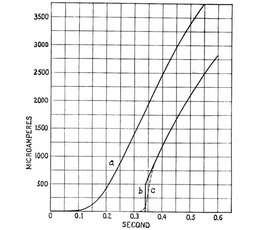
The transient solution of the problem of an ideal heavily loaded cable has been worked out by Malcolm5 and more rigorously by Carson6, who have determined the curve showing the change of current with time at one end of the cable if a steady e.m.f. is applied at zero time between the cable and earth at the distant end. Such a curve is called an "arrival curve" and for an ideal loaded cable comprising only constant distributed resistance, capacity and inductance may have a form like that shown in Curve b of Fig. 3, which is to be p. 362 compared with Curve a which is the arrival curve of a non-loaded cable. The straight vertical part of Curve b represents the "head" of the signal wave which has travelled over the cable at a definite speed and with diminishing amplitude. The definite head of the arrival curve is the most striking characteristic difference between the ideal loaded and the non-loaded cable. In the latter, as is evident from Fig. 3, the current at the receiving end starts to rise slowly almost as soon as the key is closed at the transmitting end. When an e.m.f. is applied to the sending end of the non-loaded cable a charge spreads out rapidly over the whole length, the receiving end charging up much more slowly than the sending end on account of the resistance of the intervening conductor. Hence, if a signal train consisting of rapidly alternating positive and negative impulses is applied to the sending end, the effect at the receiving end of charging the cable positively is wiped out by the succeeding negative charge before there has been time to build up a considerable positive potential and the successive alternating impulses thus tend to annul each other. In the loaded cable the effect of inductance is to oppose the setting up of a current and to maintain it once it has been established, and thus to maintain a definite wave front as the signal impulse travels over the cable. Hence, with inductive loading the strength and individuality of the signal impulses are retained and a much higher speed of signalling is possible. It should be noted that by speed of signalling is meant the rapidity with which successive impulses are sent and not the rate at which they travel over the cable. This speed of travel is actually decreased by the addition of inductance, about one-third of a second being required for an impulse to traverse the New York-Azores cable from end to end.
It should be noted that Curve b of Fig. 3 is for an ideal loaded cable in which the factors of resistance, capacity and inductance are constant. In a real loaded cable none of these factors are constant and the arrival curve cannot be simply and accurately computed. Even the capacity which is usually assumed as constant for real cables varies appreciably with frequencies in the telegraph range, and owing to the fact that gutta percha is not a perfect dielectric material its conductance, which is also variable with frequency, must be taken into account. Although the inductance of the cable is substantially constant for small currents of low frequency, it is greater for the high currents at the sending end of the cable on account of the increase of magnetic permeability of the loading material with field strength and is less at high frequencies than at low on account of the shielding effect due to eddy currents. The resistance is highly p. 363 variable since it comprises, in addition to the resistance of the copper conductor, effective resistance due to eddy currents and hysteresis in the loading material, both of which vary with frequency and current amplitude. Furthermore, there is variable inductance and resistance in the return circuit outside the insulated conductor which must be taken into account. Although it is very difficult to compute the exact arrival curve of a cable subject to all of these variable factors, an approximate calculation in a specific case like that of the New York-Azores cable shows that the arrival curve has the general shape of Curve c of Fig. 3. It will be noticed that although this arrival curve lacks the sharp definite head, characteristic of the ideal loaded cable, it still has a relatively sharp rise and that the time required for the impulse to traverse the cable is not greatly different from that of the ideal loaded cable.
Although it is difficult to take exact account of the variable characteristics of the loaded cable in the solution of the transient problem, it is easy to take account of them in the steady state or periodic analysis by means of well-known methods. If a steady sinusoidal voltage, , is applied at one end of the cable the resulting voltage, , at the distant end will be given by the equation
where is the length, , the propagation constant of the cable and , a constant which depends on the terminal impedance and which is unity in case the cable is terminated at the receiving end in its so-called characteristic impedance. The propagation constant is given by the formula,
where is the resistance, , the inductance, , the leakance and , the capacity per unit length and is times the frequency. The real part of the propagation constant, , is called the attenuation constant and the imaginary part, , the wave length constant. By separating and the amplitude and phase displacement of the received voltage relative to the sent voltage may be computed for any particular frequency and the behavior of a complex signal train may be worked out by analyzing it into its Fourier components and treating them separately. The phase shift is, however, of importance mainly as regards the shape of the received signals and their amplitude may, in general, be obtained from the attenuation constant alone. Thus if it is known that the signal shape can in any case be corrected by terminal networks there is no need to be concerned with more than the attenuation constant to compute the speed of the cable.
In the case of a cable of the permalloy loaded type, is given with an approximation7 sufficiently close for the purposes of this discussion by the equation,
For the purpose of computing it is convenient to separate it into its components, giving
where
- = copper resistance per unit length
- = eddy current resistance per unit length
- = sea return resistance per unit length
- = hysteresis resistance per unit length
The copper resistance is that determined by a direct current measurement of the loaded conductor since the resistance of the loading tape is so high and its length is so great that the current flowing longitudinally through it may be safely neglected.
The eddy current resistance is given approximately by the formula,
where is the thickness or diameter of the loading tape or wire, , the outside diameter of the loaded conductor, , the frequency, , the resistivity of the loading material, , its magnetic permeability and , a constant which depends on the form of the loading material and is in general greater for tape than for wire loading. Although it is possible to compute a value of , the value found in practice is always larger than the theoretical value which is necessarily based on simple assumptions and does not take into account such a factor as variation of permeability through the cross-section or length of the loading material. Accordingly it is necessary to determine experimentally for any particular type of loaded conductor.
The sea-return resistance may be safely neglected in the computation of slow speed non-loaded cables, but it is a factor of great consequence in the behavior of a loaded cable. By sea-return resistance is meant the resistance of the return circuit including the effect of the armor wire and sea water surrounding the core of the cable. Although the exact calculation8 of this resistance factor is too complex to be discussed here, the need for taking it into account may be quite simply explained. Since the cable has a ground return, current must flow outside the core in the same amount as in the conductor. The distribution of the return current is, however, dependent on the structure of the cable as well as on the frequencies involved in signalling. If a direct current is sent through a long cable with the earth as return conductor the return current spreads out through such a great volume of earth and sea water that the resistance of the return path is negligible. On the other hand if an alternating current is sent through the cable the return current tends to concentrate p. 366 around it, the degree of concentration increasing with the frequency. With the return current thus concentrated the resistance of the sea water is of considerable consequence. It is further augmented by a resistance factor contributed by the cable sheath. This may be better understood by considering the cable as a transformer of which the conductor is the primary and the armor wire and sea water are each closed secondary circuits. Obviously the resistances of the secondary circuits of armor wire and sea water enter into the primary circuit and hence serve to increase the attenuation. The presence of the armor wires may thus be an actual detriment to the transmission of signals.
To take account of the hysteresis resistance, , and also of the increased inductance and eddy current resistance at the sending end of the cable it is most convenient to compute the attenuation of the cable for currents so small that may be safely neglected. The attenuation thus computed is that which would be obtained over the whole cable if a very small sending voltage were used. The additional attenuation at the sending end for the desired sending voltage may then be approximated by computing successively from the sending end the attenuation of short lengths of cable over which the current amplitude may be considered constant, the attenuations of separate lengths being added together to give the attenuation of that part of the cable in which hysteresis cannot be neglected. In this computation account must, of course, be taken of the increased inductance and eddy current resistance accompanying the higher currents at the sending end.
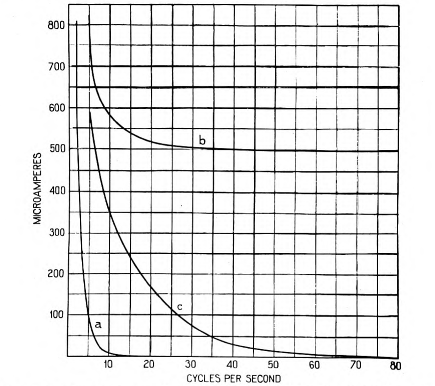
Having calculated or obtained by measurement the several resistance factors and knowing the capacity, leakance and inductance, the whole attenuation of a cable for any desired frequency may be computed and a curve drawn showing the variation of received current with frequency for a given sending voltage. This relation for a particular case is shown in Curve c of Fig. 4. Curve a shows for comparison the relation between frequency and received, current of a non-loaded cable of the same size, that is, a cable having a conductor diameter the same as that of the loaded conductor and having the same weight of gutta percha. Curve b shows the behavior of an ideal loaded cable having the same inductance, capacity and d.c. resistance as the real loaded cable of Curve c, but in which the leakance and alternating current increments of resistance are assumed to be zero.
Now, if the level of interference through which the current must be received is known, the maximum speed of signalling for the loaded cable may be obtained from Curve c. It is that speed at which the p. 367 highest frequency necessary to make the signals legible is received with sufficient amplitude to safely override the superposed interference. Just what the relation of that frequency is to the speed of signalling cannot be definitely stated, since it depends on the method of operation and code employed as well as on the desired perfection of signal shape. J. W. Milnor9 has suggested that for cable code operation and siphon recorder reception a fair value is about 1.5 times the fundamental frequency of the signals, that is, the fundamental frequency when a series of alternate dots and dashes is being sent.
Remarks on the Design of Loaded Cables
By referring again to the equation for , above, it can now be explained why high permeability is a necessary characteristic of the p. 368 loading material if a benefit is to be obtained from continuous loading. The addition of the loading material has two oppositely directed effects; on the one hand it tends to improve transmission by increasing the inductance and consequently decreasing the attenuation, and on the other hand it tends to increase the attenuation by increasing the effect of leakance and by the addition of resistance. Not only are the hysteresis and eddy-current factors of resistance added by the loading material but it must also be looked upon as increasing either the copper resistance or the capacity on account of the space it occupies. Generally it is more convenient to look upon the loading material as replacing some of the copper conductor in the non-loaded cable with which comparison is made, since by so doing all of the factors outside of the loaded conductor are unchanged. Now, if the loading material is to be of any benefit, the decrease in attenuation due to added inductance must more than offset the increase due to added resistance, including the added copper resistance due to the substitution of loading material for copper. In the limiting case the lowest permeability material which will show a theoretical advantage from this point of view is that which, as applied in a vanishingly thin layer, gives more gain than loss. For any particular size and length of cable there is a limiting value of permeability which will satisfy this condition, this limiting value being greater the longer the cable and the smaller the diameter of its conductor.10 For transatlantic cables of sizes laid prior to 1923 the minimum initial permeability required to show an advantage is higher than that of any material known prior to the invention of permalloy. Actually a considerably higher permeability than this theoretical minimum was, of course, required to make loading an economic advantage since there are practical limits to the thickness of loading material and since the cost of applying it has also to be taken into account. Further, there are limits on methods of operation imposed by loading which necessitate still higher permeability to make loading worth while.
Since the addition of loading has two opposite tendencies in its effect on attenuation, the practical design of the cable must be based on a compromise between them. Thus, to secure the maximum gain from loading a cable of a given size, the loading material should be chosen of such a thickness that the gain due to increased inductance from a slight increase of thickness just offsets the loss due to increased resistance and dielectric leakance. In practice, of course, economic considerations of the cost of various thicknesses of loading must also be taken into account.
In designing the New York-Azores cable some assumption had to be made as to the extraneous interference which would be encountered. Theoretical considerations led us to believe that the loaded cable would be no more subject to external interference than non-loaded cables. It even appeared that it would be less affected by some types of interference, for, owing to the shorter wave-length for a given frequency, a disturbance which affects a great many miles of cable simultaneously is less cumulative in its effect at the terminal of a loaded than a non-loaded cable. A reasonable assumption seemed to be that the total overall attenuation which could be tolerated for the loaded cable was at least as great as that which experience had shown to be permissible for simplex operation of non-loaded cables. This maximum permissible attenuation depends, of course, on conditions of terminal interference and no fixed value can be given as applicable to all cables. However, for average conditions of terminal interference in locations free from power line disturbances and where the cable lies in relatively deep water near to its terminal landing, a reasonable value of total attenuation constant for the fundamental frequency of cable code is about 10 (86.9 T.U.) for recorder operation and about 9 (78.2 T.U.) for relay operation. These were the approximate values assumed for the New York-Azores cable and later experience has demonstrated that they were well justified.
Distortion in Loaded Cables
Throughout all of the preceding discussion it has been assumed that the relation between attenuation and terminal interference would limit the speed of simplex operation rather than that distortion of signal shape would be the limiting factor. Although this is, in fact,11 the case with non-loaded cables it was not self-evident as regards the loaded cable, and to make reasonably certain that the speed could be determined from the attenuation-frequency relation required a demonstration that the signal distortion of a real loaded cable could be corrected by suitable terminal apparatus. One of the merits long claimed for loading was that it would reduce distortion and, indeed, an ideal loaded cable with constant inductance and without magnetic hysteresis, eddy current loss, dielectric leakance and sea return resistance would have very little distortion and would give a speed limited only by terminal apparatus. However, p. 370 a real loaded cable, the inductance of which varies with both current and frequency and in which all the above noted resistance factors are present, may give, and in general will give when operated at its maximum speed, greater distortion of signals than a non-loaded cable.
To solve the question of distortion on a purely theoretical basis required consideration of the transmission of a transient over the loaded cable. This was made extremely difficult by the existence of numerous possible causes of signal distortion, the effects of which could only be approximated in the solution of the transient problem. In addition to the distortion resulting from the rapid increase of attenuation with frequency due to the various sources of alternating current losses, distortion peculiar to the magnetic characteristics of the loading material had also to be taken into account. There are several types of magnetic distortion to be concerned about. First, there is the production of harmonics as a result of the non-linear magnetization curve of the loading material; second, there is a possible asymmetrical distortion due to hysteresis, and third, there is a possible modulation resulting from the superposition of signals on each other, that is, in effect, a modulation of the head of the wave of one impulse by the tail of the wave of a preceding impulse. The first two of these are effective at the sending end of the cable and the third near the receiving end.
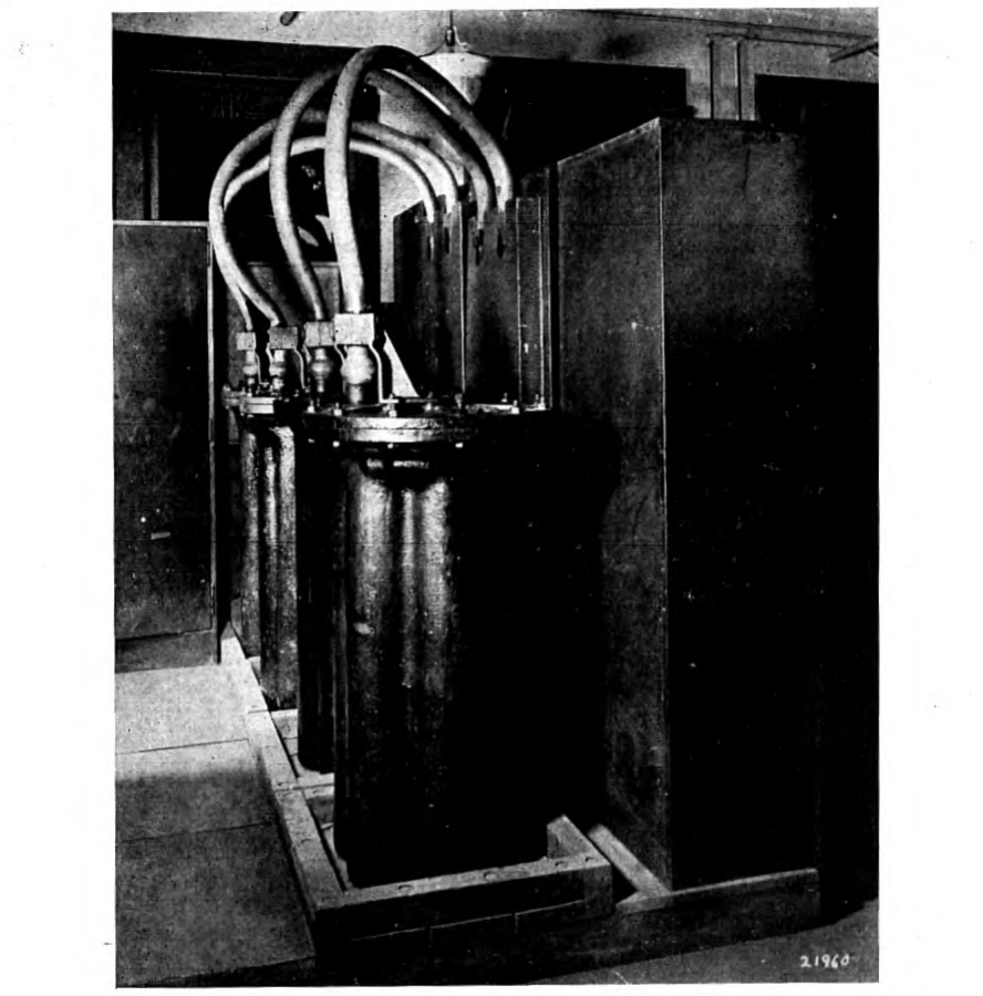
A computation of distortion, including the peculiar magnetic effects, by a steady state a.c. method based on measurements of short loaded conductors indicated that the cable should operate satisfactorily with ordinary sending voltages. Further evidence that none of these various types of distortion would be of serious consequence and that the distortion of a loaded cable could be corrected by terminal apparatus, was obtained by experiments with an artificial line constructed to simulate closely, with regard to electrical characteristics, the type of loaded conductor with which we were then experimenting. This artificial line was loaded with iron dust core coils which served the purpose admirably, not only as regards inductance and alternating current resistance but also as regards magnetic distortion. Iron dust is, of course, very different in its magnetic characteristics from permalloy. However, owing to the large number of turns on a coil, it is operated at much higher field strengths and on a part of the magnetization curve corresponding approximately to that at which permalloy is operated on the cable. The case for magnetic distortion was in fact a little worse with the p. 371 artificial line than with the then proposed cable. Fig. 5 shows a photograph of the artificial line, the coils of which are in the large iron pots and the resistance and paper condenser capacity units of which are in the steel cases. This line was equivalent to a 1,700 nautical mile cable loaded with 30 millihenries per n.m. and over it legible signals were secured at speeds up to more than 2,600 letters per minute. Such a speed of operation was quite beyond the range of the then available telegraph instruments, and accordingly special transmitting and receiving instruments were required. The multiplex distributor of the Western Electric printing telegraph system proved an excellent transmitter for experimental purposes and, for receiving, p. 372 use was made of a combined vacuum tube amplifier and signal shaping network, the signals being recorded on a string oscillograph. Fig. 6 shows part of a test message received over the loaded artificial cable at a speed of 2,240 letters per minute.
The results of the tests with the artificial loaded cable were entirely in agreement with our calculations and showed that it was possible to obtain satisfactory signal shape with a coil-loaded cable having alternating current resistance and distortion factors approximating those of the permalloy-loaded cable. The exact behavior of the proposed cable, including such factors as sea-return resistance and a somewhat variable distributed inductance, could not, of course, be duplicated without prohibitive expense. The approximation was considered, however, to be sufficiently good to justify proceeding with a loaded cable installation so far as questions of signal shaping were concerned. It is interesting to note that the factor which limited the operating speed of the artificial loaded cable was one which is not present in a continuously loaded cable but which would possibly be a serious factor in the operation of a coil loaded cable, namely the oscillations12 resulting from the finite size and separation of the inductance units.

Operation of Loaded Cables
With the completion of the artificial loaded cable tests there was still one principal question of transmission which had to remain unanswered until a cable had been installed. This was the question of balancing the cable for duplex operation. Ordinary submarine cables are generally operated duplex, the total speed in the two directions being usually from about 1.3 to 2 times the maximum simplex or one-way speed. Except in cases where the external interference is very bad, the limiting speed of duplex operation is determined by the accuracy with which an artificial line can be made the electrical equivalent of the cable. Ordinarily the artificial line is p. 373 made up only of units of resistance and capacity arranged to approximate the distributed resistance and capacity of the cable. Sometimes inductance units are added to balance the small inductance which even a non-loaded cable has. In the actual operation of cables, artificial lines are adjusted with the greatest care and a remarkable precision of balance is obtained. This is necessary because of the great difference in current amplitude of the outgoing and incoming signals, the former being of the order of 10,000 times the latter. It is quite obvious that it will be much more difficult to secure duplex operation with a loaded than with an ordinary cable, since not only do the copper resistance and the dielectric capacity have to be balanced, but the artificial line must also be provided with inductance and alternating current resistance. Also the sea-return resistance and inductance which vary with frequency must be balanced.
In view of these difficulties it will probably be impossible to get as great a proportionate gain from duplex operation of loaded cables as is secured with ordinary cables. However, it is quite evident that it will be possible to secure duplex operation at some speed, since, with loaded as with non-loaded cables, the ratio of received to sent current increases rapidly as the speed is reduced and on this account it is much easier to duplex the cable at low speeds than at high. To make duplexing worth while on a cable with approximately equal traffic loads in both directions it is in general only necessary to get a one-way duplex speed half as great as the simplex speed. In fact in some cases the operating advantages of duplex would warrant even a slower duplex speed. On the other hand, there are cables on which the traffic is largely undirectional through most of the day and which would accordingly require a one-way duplex speed somewhat higher than half the simplex speed to justify duplex operation. Whether a sufficiently great speed of duplexing could be secured to justify designing a cable on the basis of duplex operation could not be judged in advance of laying the first cable, and accordingly it was decided to engineer that cable on the basis of simplex operation.
Although it was expected that the new cable might at first have to be operated simplex it should not be supposed that any great difficulty or loss of operating efficiency was anticipated on this account. The speed of the New York-Azores cable is so great that to realize its full commercial advantage practically requires working it on a multi-channel basis as, for example, with a Baudot code, multiplex system, similar to that used on land lines. Such a system may be conveniently adapted to automatic direction reversal and with this modification most of the common objections to simplex operation are p. 374 removed. Indeed, simplex operation may in this case possess a real advantage over duplex from the commercial point of view since it permits dividing the carrying capacity of the cable most efficiently to handle the excess of traffic in one direction.
Although means have been made available for making efficient use of the loaded cable it should be recognized that the method of operation best suited to satisfy commercial demands must be determined from future experience with cables of the new type. This is especially true with regard to relatively short cables. The discussion of the loaded cable problem in this paper has been confined wholly to the realm of long ocean cables where the limitations of the cable rather than terminal equipment or operating requirements determine the best design. This is the simplest case and the one which at present seems to show the greatest gain from loading. Where traffic requirements are limited and where there is no prospect of ever requiring higher speed than can be obtained with a non-loaded cable of reasonable weight, the advantage of loading is less and becomes smaller as the weight of non-loaded cable which will accomplish the desired result decreases. It should not be concluded, however, that loading will not find important application to short cables. Many short cables are parts of great systems and must be worked in conjunction with long cables. In such cases it may pay to load short sections where otherwise loading would not be justified. Permalloy loading also offers great possibilities for multiple-channel carrier-telegraph operation on both long and short cables and with this type of operation in prospect it is too early, now, to suggest limits to the future applications of permalloy to cables or to predict what will be its ultimate effect on transoceanic communication.
Notes
-
Presented before the A. I. E. E., June 26, 1925. ↩
-
Jour. Franklin Inst., Vol. 195, pp. 621-632, May 1923; B. S. T. J., Vol. II, No. 3, p. 101. ↩
-
The true initial permeability is slightly higher. To compute it, account must be taken of the fact that, contrary to what has been sometimes assumed, the magnetic lines of induction in the tape do not form closed loops around the wire but tend to follow the tape in a helical path. The pitch of the helical path of the lines of induction is slightly less than that of the permalloy tape with the result that a line of induction takes a number of turns around the conductor, then crosses an airgap between two adjacent turns of tape and continues along the tape to a point where it again slips back across an airgap. O. E. Buckley, British Patent No. 206,104, March 27, 1924, also K. W. Wagner, E.N.T., Vol. I, No. 5, p. 157, 1924. ↩
-
The idea of improving the transmission of signals over a line by adding distributed inductance to it originated with Oliver Heaviside in 1887 (Electrician, Vol XIX, p. 79, and Electromagnetic Theory, Vol. I, p. 441, 1893), who was the first to call attention to the part played by inductance in the transmission of current impulses over the cable. He suggested as a means for obtaining increased inductance the use of iron as a part of the conductor or of iron dust embedded in the gutta percha insulation. He also proposed inserting inductance coils at intervals in a long line. Other types of coil loading were proposed by S. P. Thompson (British Patent 22,304—1891, and U. S. Patents 571,706 and 571,707—1896), and by C. J. Reed (U. S. Patents 510,612 and 510,613—1893). M. I. Pupin (A. I. E. E. Trans., Vol. XVI, p. 93, 1899, and Vol. XVII, p. 445, 1900) was the first to formulate the criterion on the basis of which coil loaded telephone cables could be designed. Continuous loading by means of a longitudinally discontinuous layer of iron covering the conductor was proposed by J. S. Stone in 1897 (U. S. Patent 578,275). Breisig (E. T. Z., Nov. 30, 1899) suggested the use of an open helix of iron wire wound around the conductor and Krarup (E. T. Z., April 17, 1902) proposed using a closed spiral so that the adjacent turns were in contact. J. H. Cuntz (U. S. Patent 977,713 filed March 29, 1901) proposed another form of continuous loading. Recent general discussions of loaded telegraph cable problems have been given by Malcolm (Theory of Submarine Telegraph and Telephone Cable, London, 1917) and by K. W. Wagner (Elektr. Nachtr. Tech., Oct., 1924). ↩
-
Theory of the Submarine Telegraph and Telephone Cable, London, 1917. ↩
-
Trans. A. I. E. E., Vol. 38, p. 345, 1919. ↩
-
For accurate computation of attenuation the complete formula for must be used. ↩
-
See Carson and Gilbert, Jour. Franklin Inst., Vol. 192, p. 705, 1921; Electrician, Vol. 88, p. 499, 1922; B. S. T. J., Vol. I, No. 1, p. 88. ↩
-
Journal A. I. E. E., Vol. 41, p. 118, 1922. Transactions A. I. E. E., Vol. 41, p. 20, 1922. ↩
-
See British Patent No. 184,774—1923, to O. E. Buckley. ↩
-
Recent work of J. R. Carson (U. S. Patent 1,315,539—1919) and R. C. Mathes (U. S. Patent 1,311,283—1919) has shown that with the combined use of vacuum tube amplifiers and distortion correcting networks, distortion in non-loaded cables can be compensated to any desired degree. ↩
-
Carson, Trans. A. I. E. E., Vol. 38, p. 345, 1919. ↩
